Arcade Posts

Posts having to do with Arcade Machines and Pinball Machines!

Hey Everyone,

I wanted to make a Total Nuclear Annihilation shirt to wear to Expo this year and I was turned onto this site.  If you would like one, they are available below for $19.14.  These are only going to be available for a few weeks until the campaign is over.  Any profit made from these shirts is automatically donated to the American Cancer Society by TeeSpring.com.  If I see you wearing one at Expo, my friend Doug and I will give you high fives, and I am sure some others will too.  🙂

Hope to see you guys/gals at Expo!

https://teespring.com/totalannihilationpinball


front

back

Hey Everyone,

I know it has been a while since my last update.  I have been working very hard on the machine getting it ready for public viewing at Expo 2016 in October.  I have done a bunch of stuff to the game, but unfortunately, I am not going to show it here.  You are just going to have to come out to Expo and see it for yourself.  I promise I will get a bunch of pictures during Expo for those of you that cannot make it.

I have also been working on the story for the game, so here is a little introduction.  The year is 1988.  You will be traveling from this time into the distant future to stop a civilization from discovering reverse time travel.  This civilization is pretty advanced, but their weak point is that they run nuclear power as their main source to the power grid.  You will need to activate and destroy all 9 main reactors that they have on the island.  Unfortunately, you will not be able to return.

Total Nuclear Annihilation will have art, music and sound effects with a 1980’s vibe.  The color scheme is Neon Green, Neon Pink, and Orange.

Below is a glimpse at a few of the attract mode screens.  These may change in the future, who knows…  Looking forward to seeing you guys and gals at Expo!  Enjoy!

TA Main3

SG_TA

Hey Everyone,

Just wanted to post a quick update.  When I was describing my sound system tuning process to a friend, it occurred to me that this could be a pretty cool little update.   I am going to keep it semi-simple as this can be a wormhole of confusing information.

So here is what is going on.  Whenever you have a very powerful sound system that you hobbled together yourself, it is pretty risky to just tune your subwoofers by ear, especially if the output of your amp is close to the RMS rating of your subwoofers.  You can easily blow up a speaker by sending clipped output signal to them from the amp.

What is a clipped signal?  What does it look like?  For this conversation, we are going to pretend that our sound is a perfect sine wave.  The image below shows our perfect sine wave on the left.  On the right side, you can see that the sine wave is now flattened at the top and bottom.  This is called clipping.

Image credit goes to http://modernmixing.com/

Image credit goes to http://modernmixing.com/

Clipping happens when an audio signal is pushed louder than the amp can handle, so some of the data is cut off from the signal itself.

Now, back to my machine…  What I need to do is make sure that none of the audio signals are clipping on my machine, but still drive the amp and subwoofer as hard as possible.  So here are the high level steps that I took to verify that everything was ok.

  1. I created a sound sample which was a perfect sine wave running at 50hz (50 cycles per second) and set it to be the default music on the Total Annihilation machine.  (see image below)
    50hz
  2. I then disconnected the audio cable from the computer to the subwoofer amp and hooked up my oscilloscope to the output signal from the computer.  This allowed me to physically view the sound wave on my screen, you know, with my eyes.  This is called checking the pre-amp signal (in case you wanted to know).
  3. I then started a game and took a look at the 50hz sound wave that was now playing.  You can see from the image below that the signal is nice and smooth (no clipping).  Yay!
    sine-wave
  4. Next I plugged the computer audio cable back into the subwoofer amp and disconnected the subwoofer.
  5. The next thing I did was turn down the amp gain all the way to 0% (this is important).
  6. The oscilloscope was then hooked up to the high level output of the subwoofer amplifier, just like how the speaker is hooked up.
  7. I started another game to get the 50hz signal playing.
  8. Then I turned the gain amp up slowly until I could start seeing the sine wave.  I kept going until I saw a bit of clipping in the signal and then backed it down slightly under that limit.  This is simply called the amplifier signal (post amplified signal).
  9. Success!  This now has set my amp to it’s maximum clean output and I will not have to worry about blowing the (not cheap) subwoofer in my game***.   ***Yes, I could technically still blow it, but we do not have to talk about that now…
    20160622_192517

OK, OK, so there are a TON of technical details and nuances that I purposely left out of this post as it would have made it not fun to read.

Well, that is about it.  You now know how to properly check your audio amps for clipping.  All you need is some time and an oscilloscope.  🙂  Also, the sound system has never sounded so good in Total Annihilation.

See you guys/gals at Expo 2016!

Hey Everyone,

I know it has been a while since my last update, but I have made some MASSIVE progress over the past month.  I currently have the game completely wired up and SkeletonGame running!  Yes, my game flips and plays multiplayer games.  It also keeps track of some basic scoring!  So you are probably asking what the hell is SkeletonGame.  It is a framework for P-ROC written by a good friend Michael Ocean.  It is used as a starting point for people wanting to build a custom or re-themed game using PyProcGameHD.  I will be using SkeletonGame for my base game and helping the team improve the framework as I go.

More info on SkeletonGame here: http://www.skeletongame.com

Well, so let’s check out some chronological photos!!

Here is a dangerous photo of my 48v capacitor bank.  I have shown pictures of this in the past, but not powered up in the machine.  This capacitor bank acts as a smoothing circuit for my 48v line when coils fire.  This will ease the current spike to the power supply.  The little red LED on board is a warning light telling me that the capacitors are at full charge and to not touch it.  This is pretty high voltage and could definitely cause some problems if it was instantly discharged onto my hand.  🙂

20160501_144833

Here is a shot of some LED color testing I was doing on the playfield.  Just making sure all the wiring was OK!

20160509_203957

Below is a quick shot of the coil test service menu in this early version of SkeletonGame.  This version will be upgraded to a better version soon when Josh Kugler merges his version with SkeletonGame.

20160516_200938

Here is the beginning photos of the Sub Chamber that will be on the inside of the cabinet in Total Annihilation.  This is basically a small bandpass box that houses an 8″ subwoofer that fires into a sealed chamber.  The majority of the subwoofer sound will exit the bottom of the cabinet through a 4 inch port hole on the open side of the chamber.

I have already done a bunch of testing with this and 2 blown subwoofers later and a new Kicker car amplifer, I decided to stick with pure mobile audio components.  I am using a Kicker brand subwoofer and amp for this setup.  Oh, and another 12v supply that can provide up to 55 amps of current.

This is a screenshot of one of the CNC CAM setups I programmed for the Sub Chamber.

Sub Chamber CAM

Starting to assemble!

20160530_184607

Test fitting into cabinet.

20160603_191819

DONE!

20160604_135052

I will be using the Dutch Pinball suite to build some of my lampshows for this project.  Below is the base image that I use for that process to map the insert and GI lamps.

20160604_143025

Below is a quick video of my test attract mode.  It is basically cycling the colors and putting random colors to each lamp.  Kind cool eh?


Now to finish this off, here are a bunch of cool glamour shots of my playfield lit up in attract mode!  Hope you enjoyed the update!

20160612_174001 20160612_174019 20160612_174023 20160612_174041 20160612_174044 20160612_174053 20160612_174101 20160612_174120

Hey Everyone,

It’s been a while, but I promise you a great update.  I have been making a large amount of progress on the playfield wiring and other various items on the checklists.  Check out the progress below!

I finally got both of my controlled gates built and installed!  These are using coils under the playfield to pull them up as needed.  This will be a very cool feature of the game which will allow me to open the orbits on the fly.

20160321_194214

My LED segments are alive!  These are really cool looking in person.  I will be able to display ball save countdown seconds along with linking them to my lamp shows to do some really cool stuff.

20160323_192653

Making progress on the wiring of the breakout boards and the RGB LED boards.

20160324_201518

Here is a closeup of one of my RGB breakout boards.  This connects directly to the PD-LED and then has headers to connect to the RGB LED boards.  Pretty handy little PCB.

20160325_211150

More progress on the wiring.  You can see I am starting to run the switch harnesses from the switches to the SW16 boards just off the left side of the image.

20160329_212620

OK, it is starting to get really crazy here.  This PCB is a custom shield that houses an Arduino Nano that will control my 4 numeric Bally displays.

20160418_182724

This board below is a pretty dangerous one…  This is my 48v filter board.  Basically, it will smooth out the 48v dips when coils fire by charging up these large capacitors and pulling a large amount of current quickly from them instead of all from the power supply directly.   This will also make my 48v line in my machine more dangerous since these capacitors can discharge a large amount of current very quickly into, let’s say, my hand.  😐

20160418_190024

This is one of the smallest custom PCBs that I have built for this project.  This is an interface board for the emergency beacon that lives on top of my backbox.  It allows me to test and to change the pre-programmed patterns without the game running.  Obviously, a banana for scale…

20160418_192338

Ok, here is where it starts getting pretty cool in the display department…  These displays in the picture are being controlled by the Arduino Nano using some code written by Mr. Jim Askey of MyPinballs.com.  These are now ready to go!

20160418_214359

Of course, I could not leave the code as it was.  I created a very cool little startup test sequence that will show up upon initial boot.  Video below.

I have been covering most of my wires with black wire wrap to keep it clean, but these are just too good looking to cover up.  These are the plugs that lead to one of the banks of coils on my playfield.

20160428_211235

And for the final pictures of the update…  You guys aren’t going to believe this, but I successfully completed all the under playfield wiring.  This includes all serial connections, power connections, switches, coils, and lamps.  I am pretty much done under there.  Now onto the cabinet!

Here is a picture of the playfield with all the inserts lit up at full power!

20160429_224838

And finally, below is a full res picture of the bottom of my playfield.  Feel free to inspect away!  🙂

20160429_220810

Hope you enjoyed the update, until next time!

Hey Guys and Gals,

I know it has been a while since the last update, but I am making awesome progress on the machine.  Not too much to talk about, but I have a bunch of pictures to show all the progress.  Check it out!

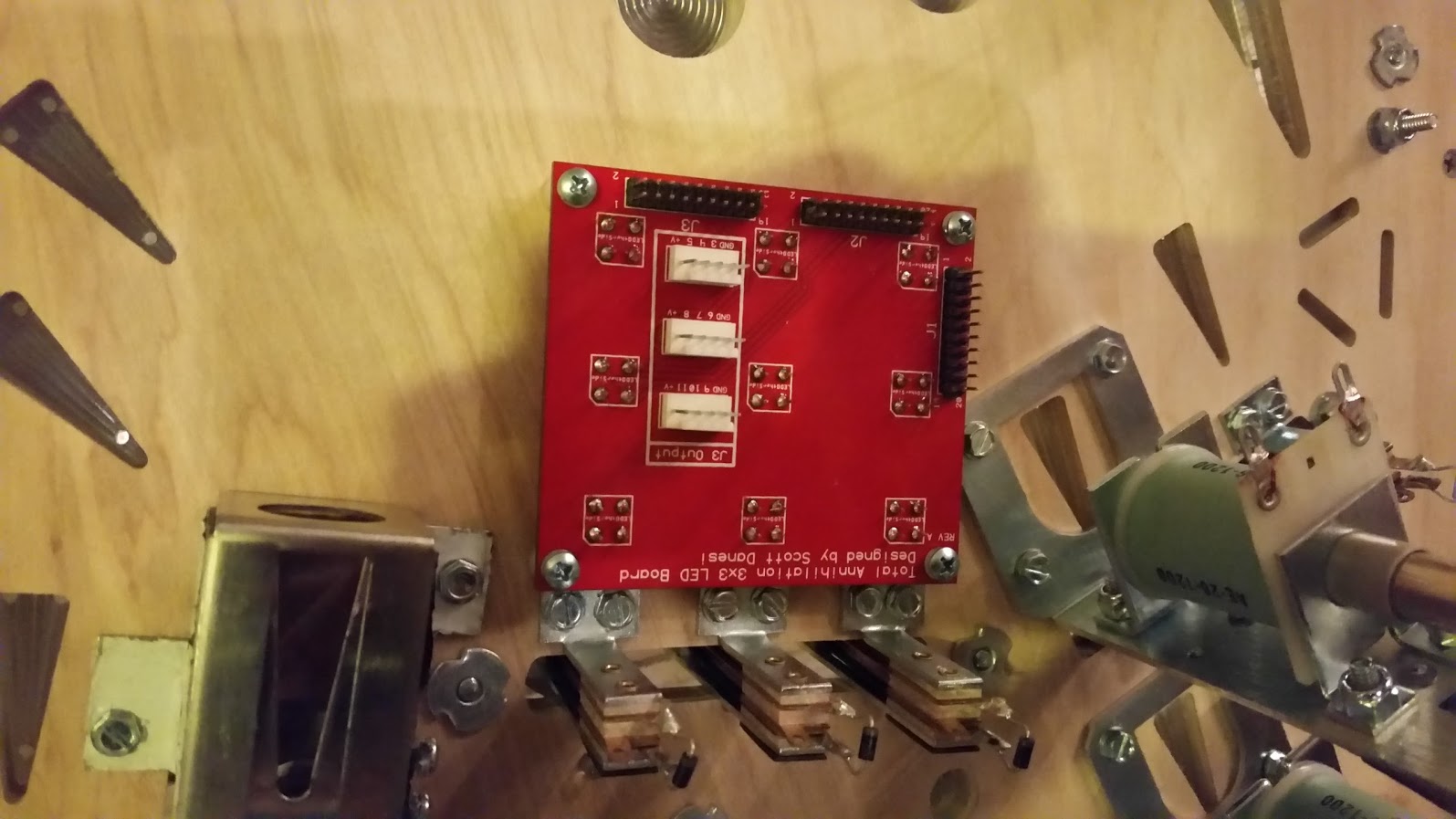
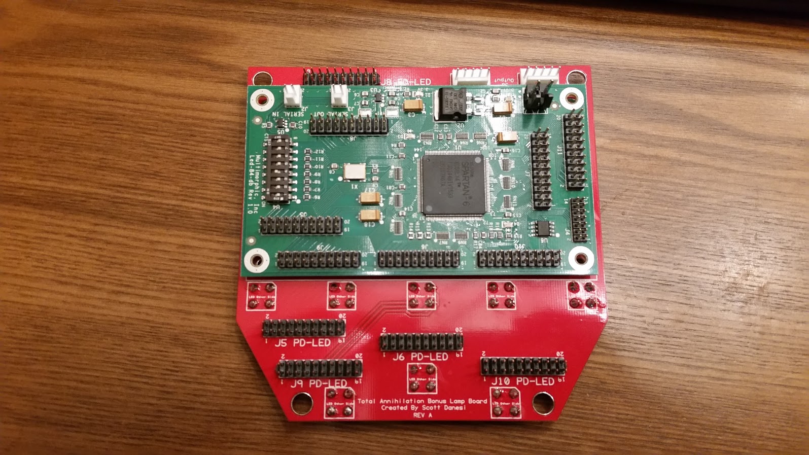
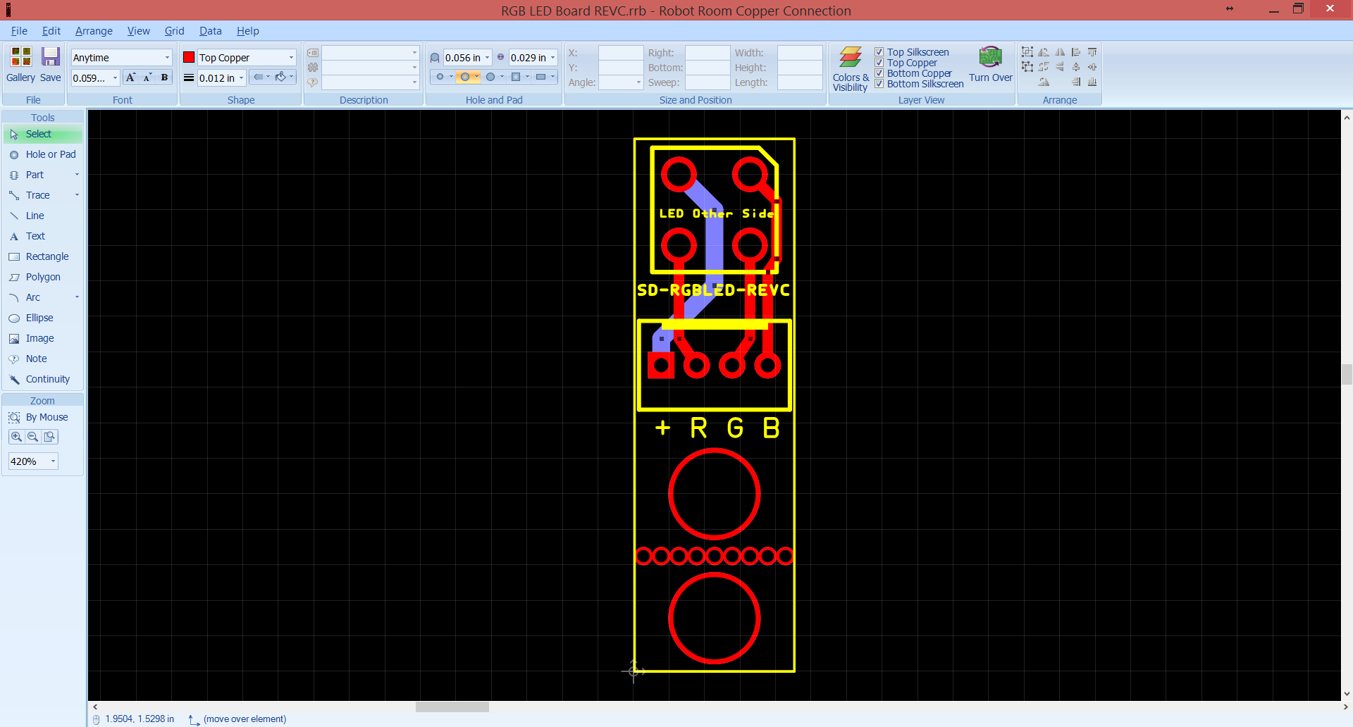
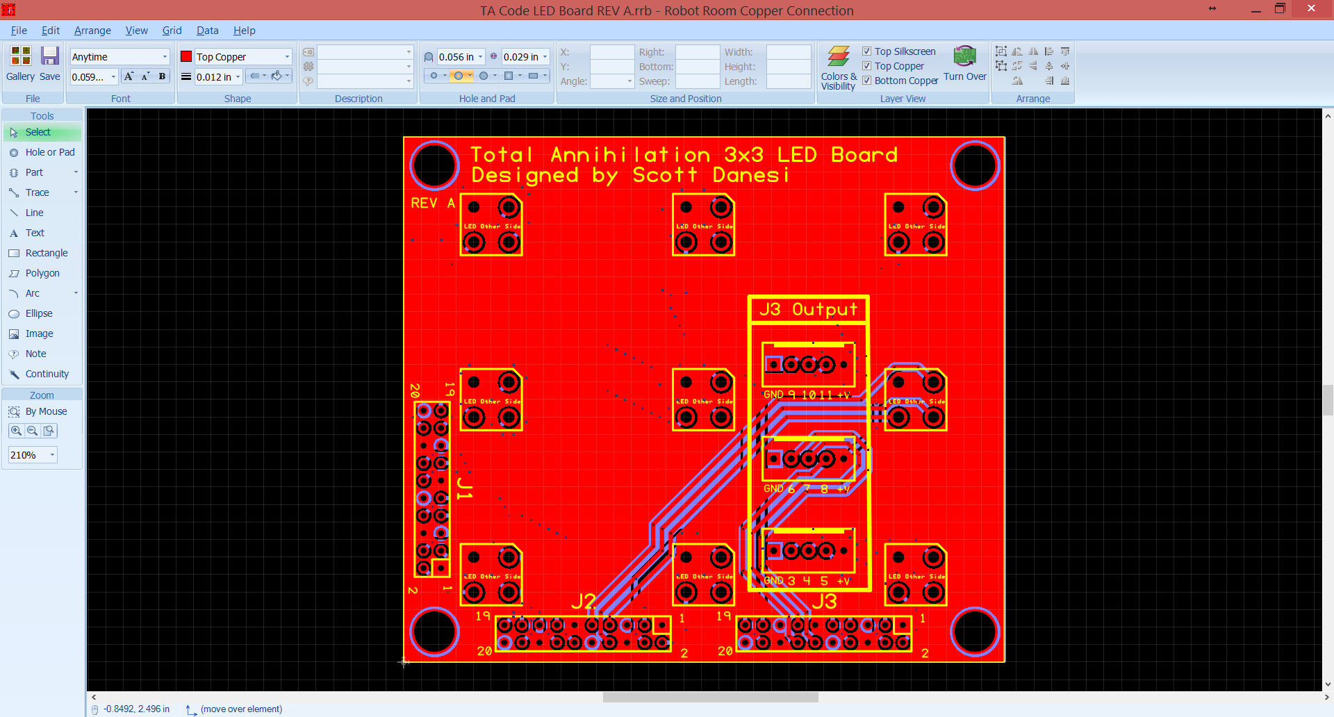
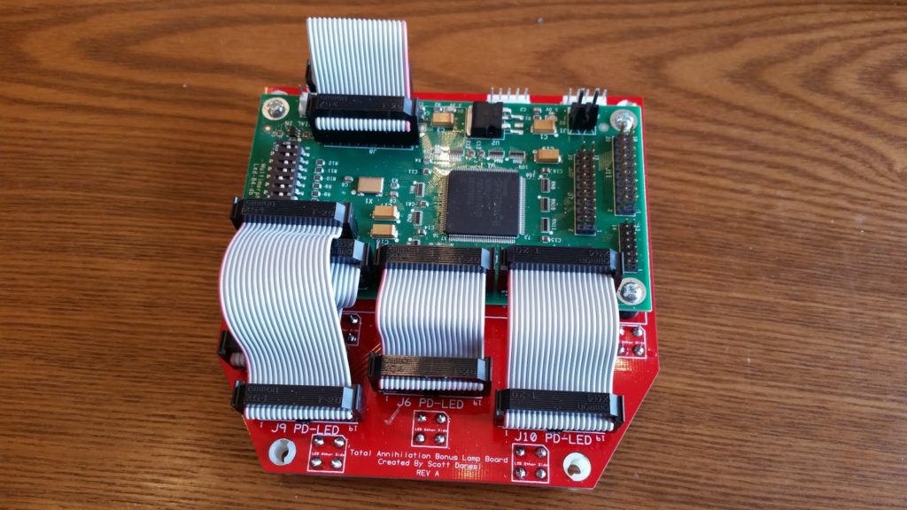
Circuit boards are here and I got a chance to populate and mount some of them pretty quickly:

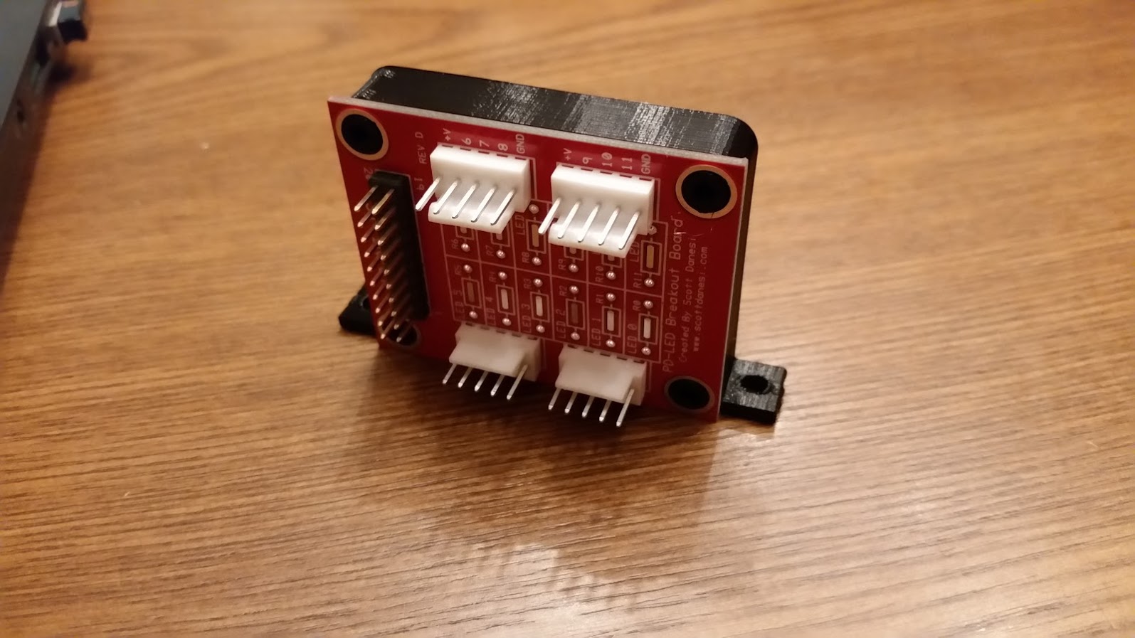
This is the 3×3 matrix PCB with direct PD-LED input headers.  Less wires = good.

20160224_191313

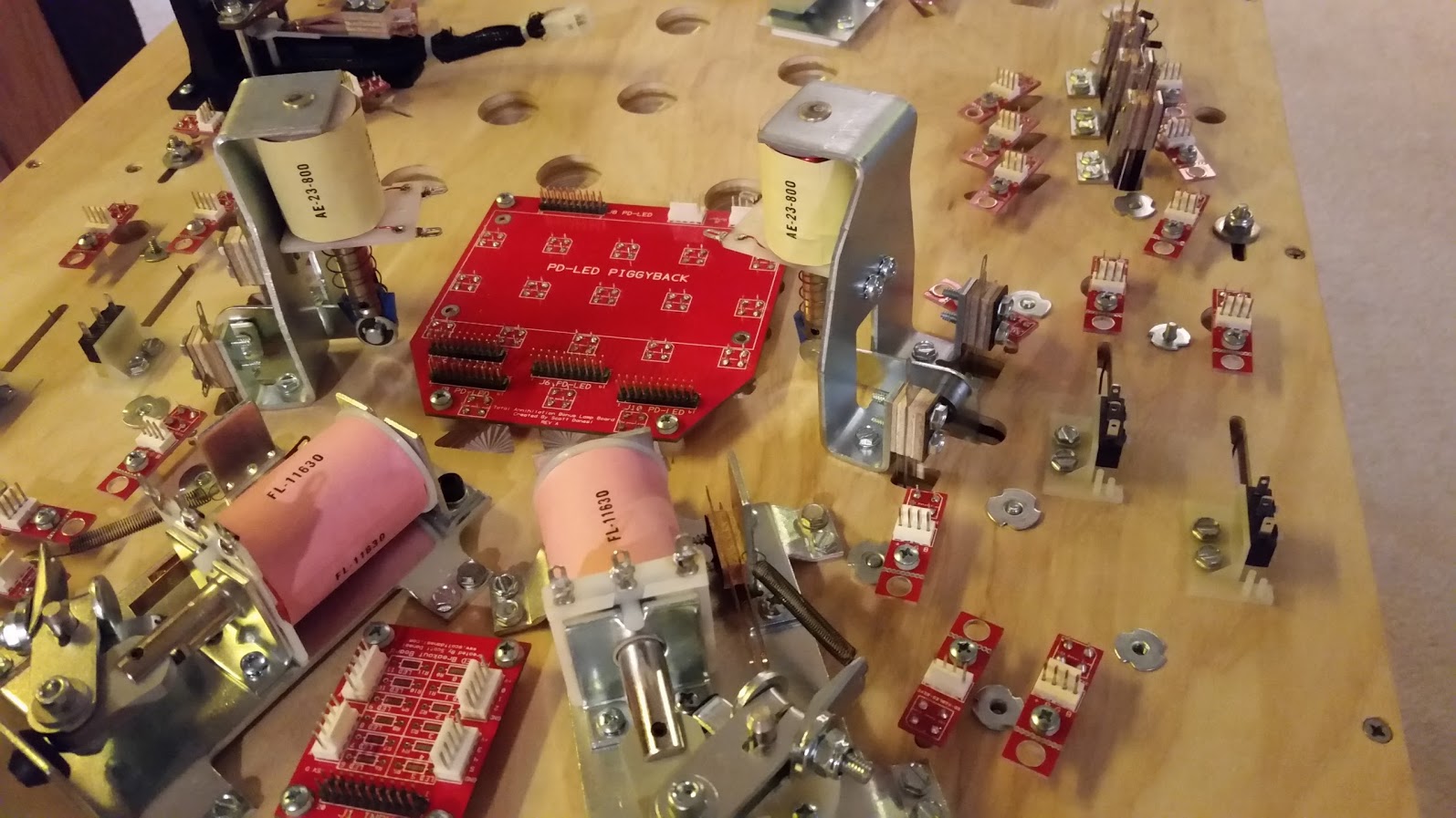
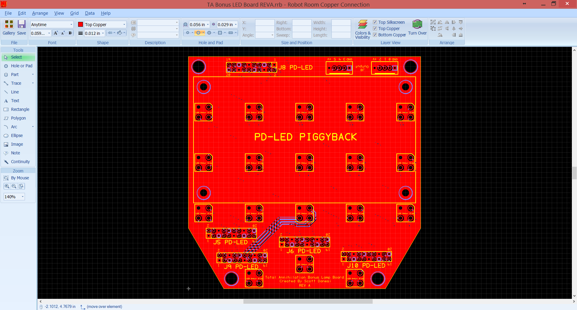
Here is the Bonus LED PCB with the PD-LED piggyback.  I was just test fitting in this picture.

20160224_213554

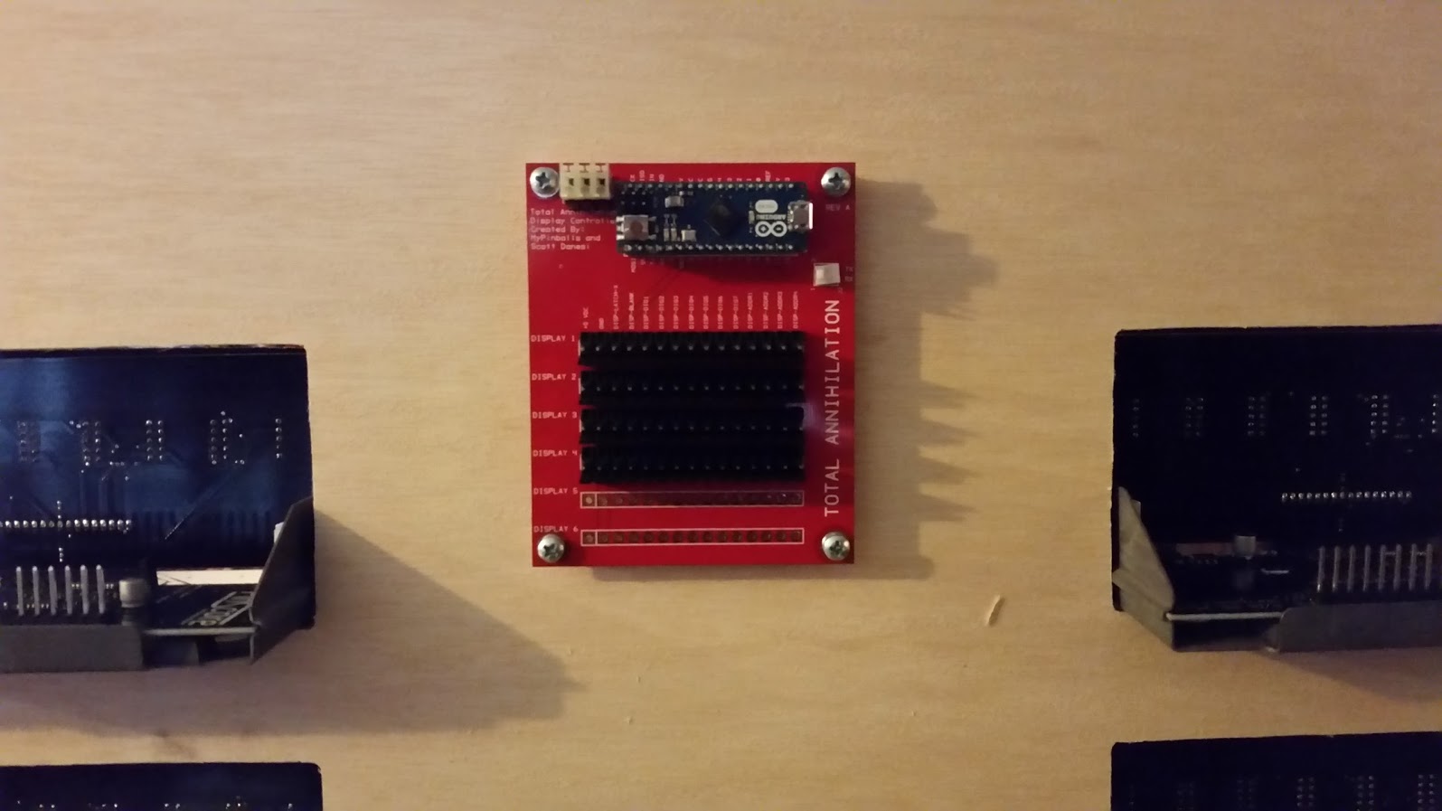
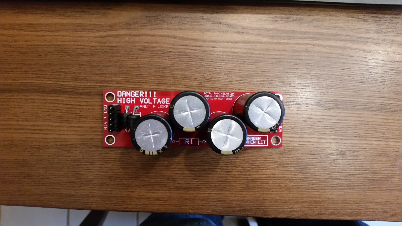
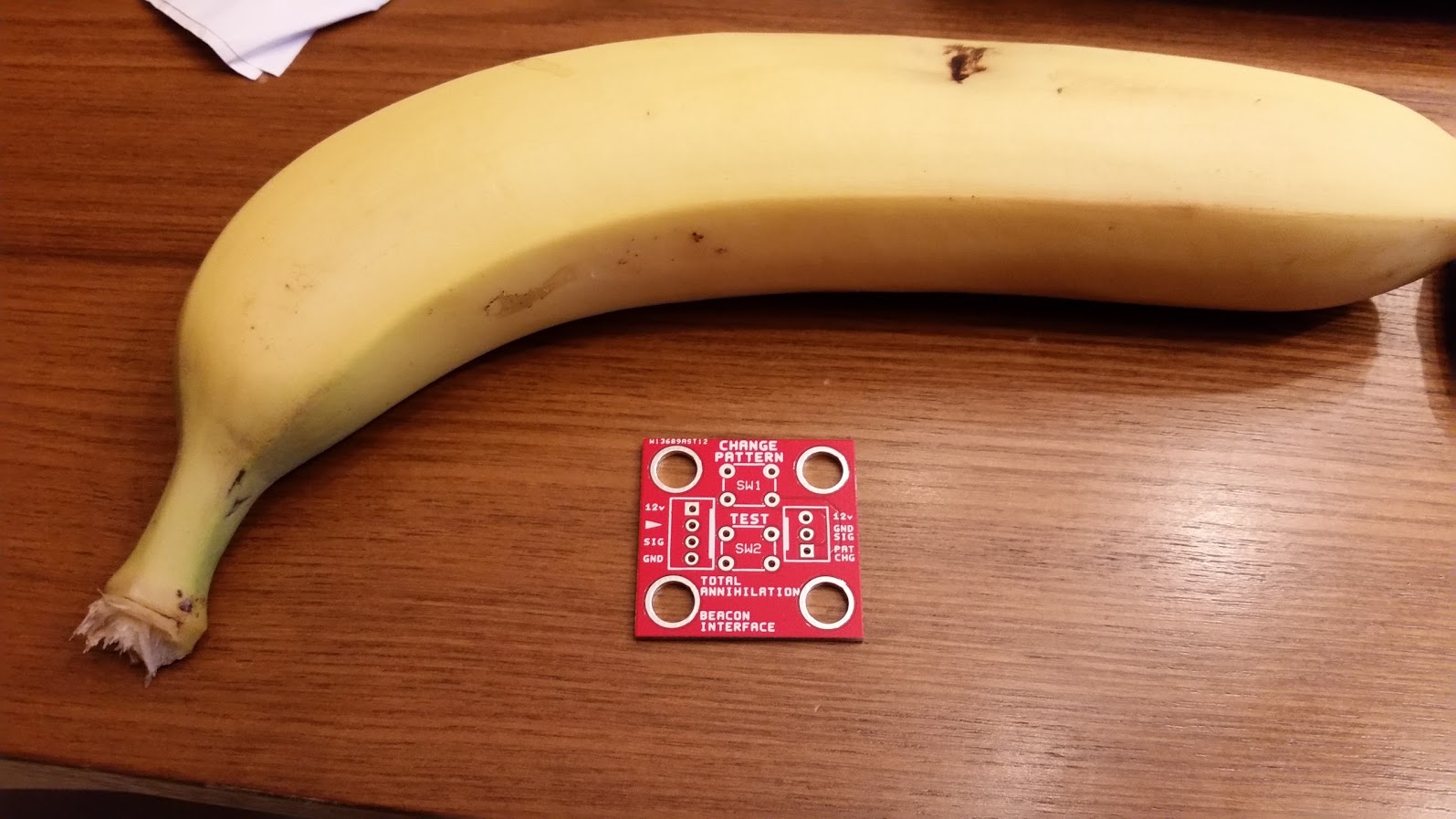
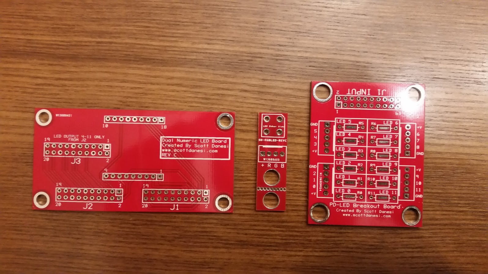
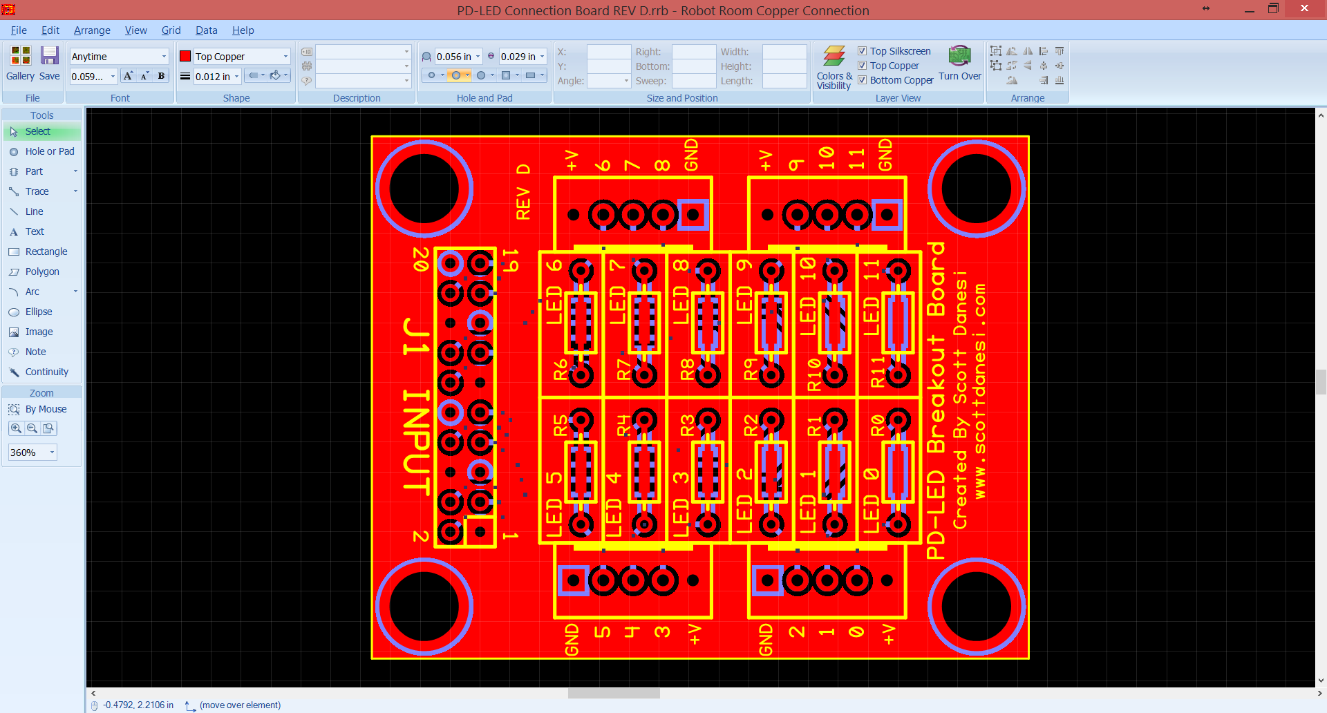
The other boards turned out great!

20160225_175518

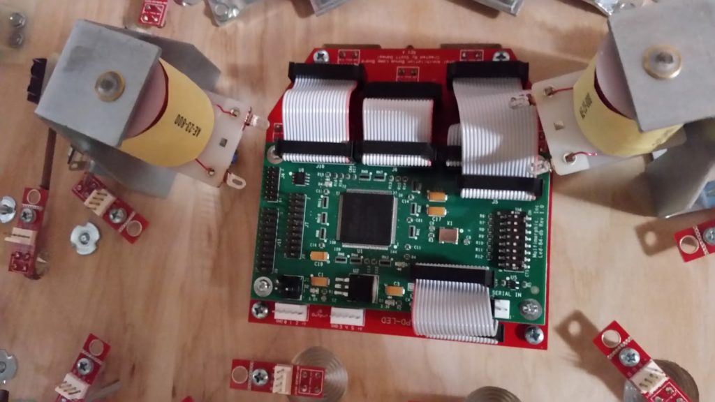
Starting to mount the custom PCBs to the bottom of the playfield.

20160305_125153

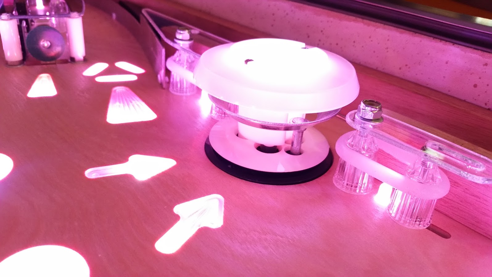
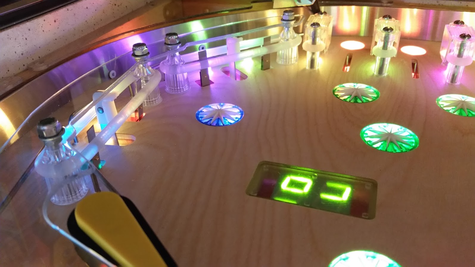
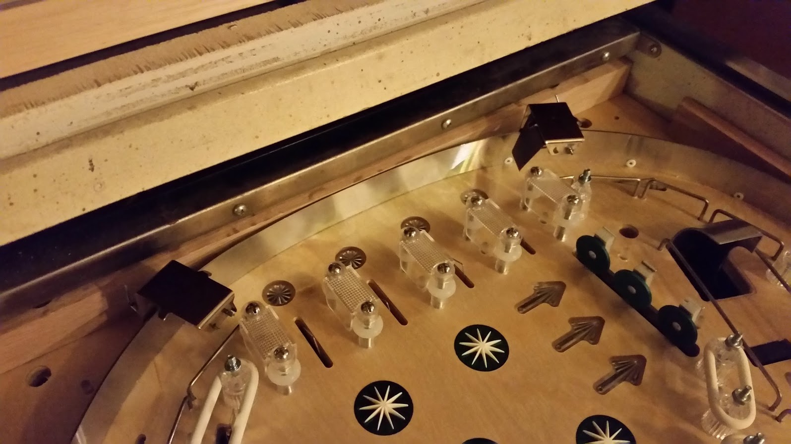
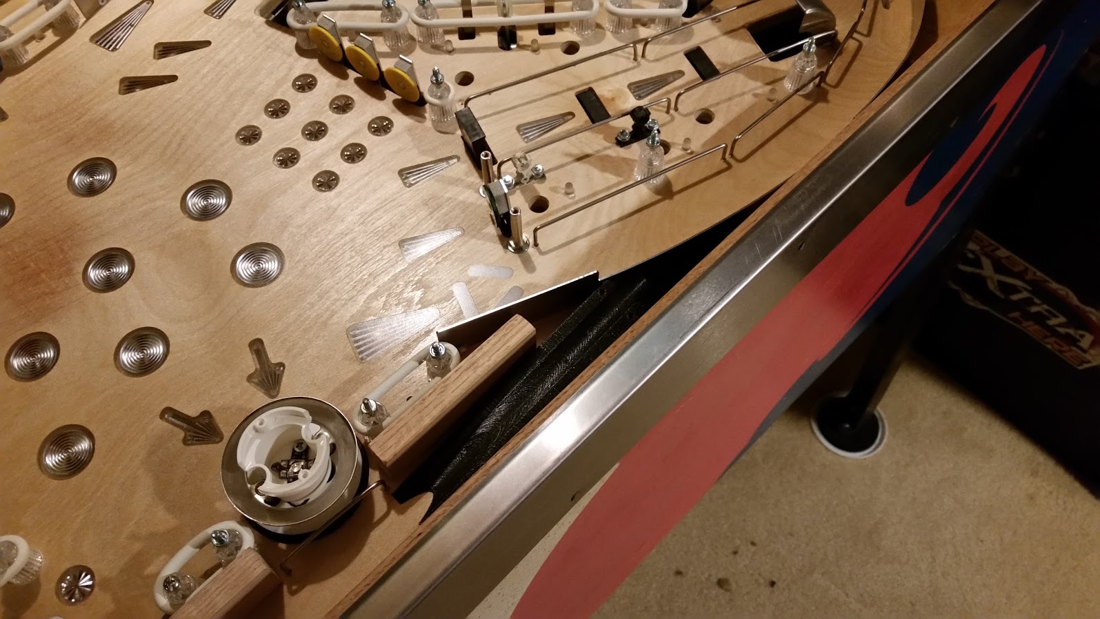
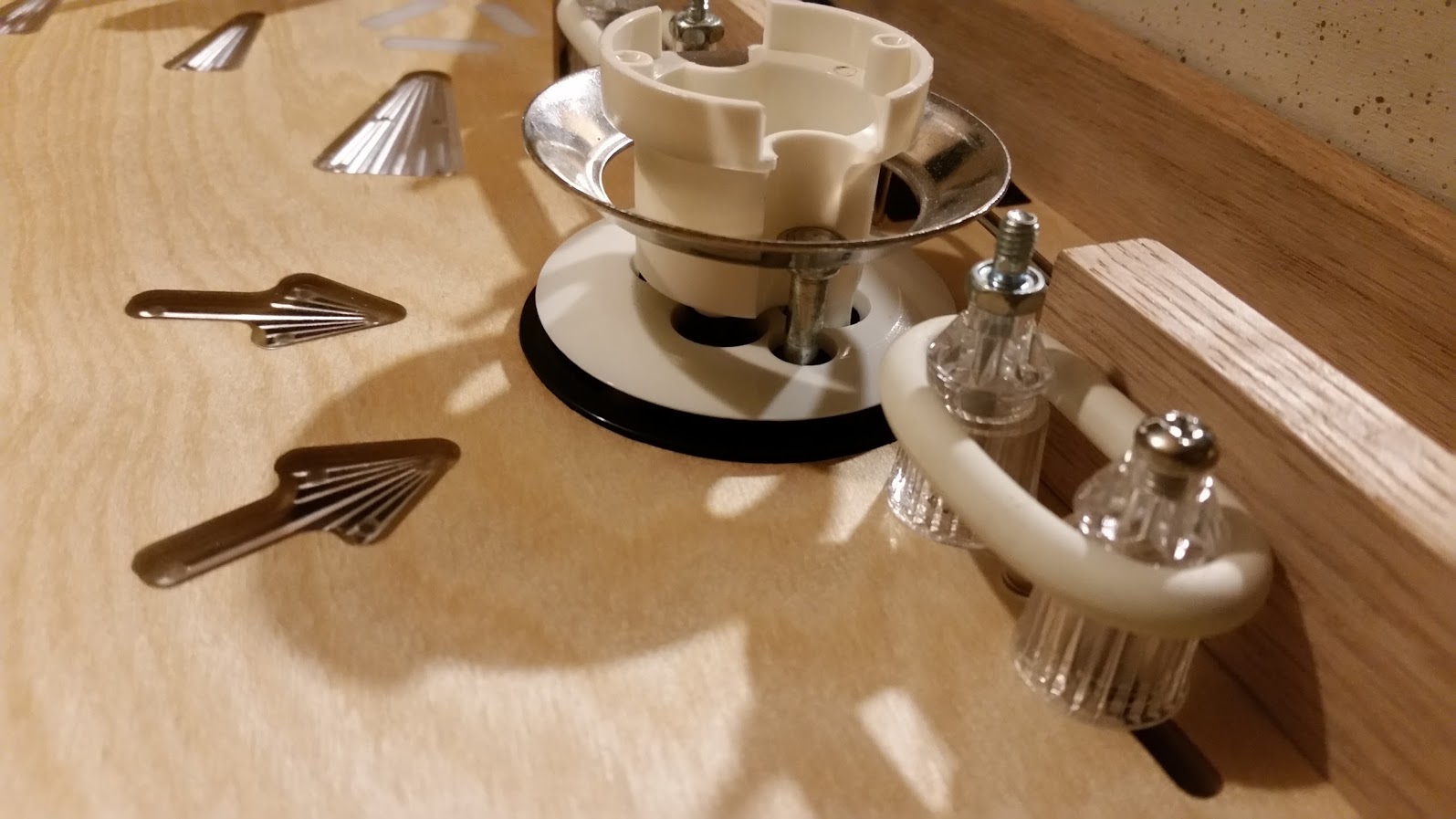
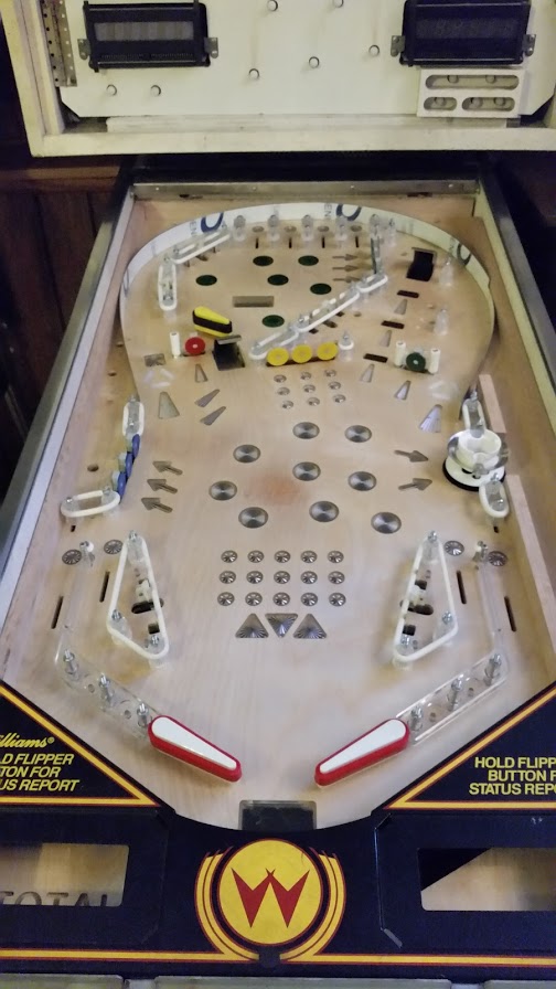
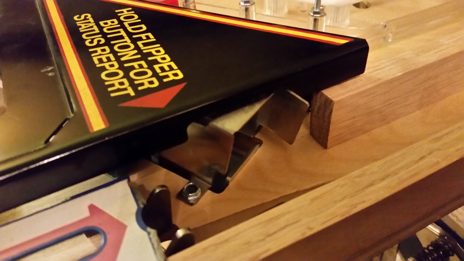
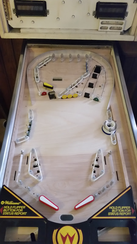
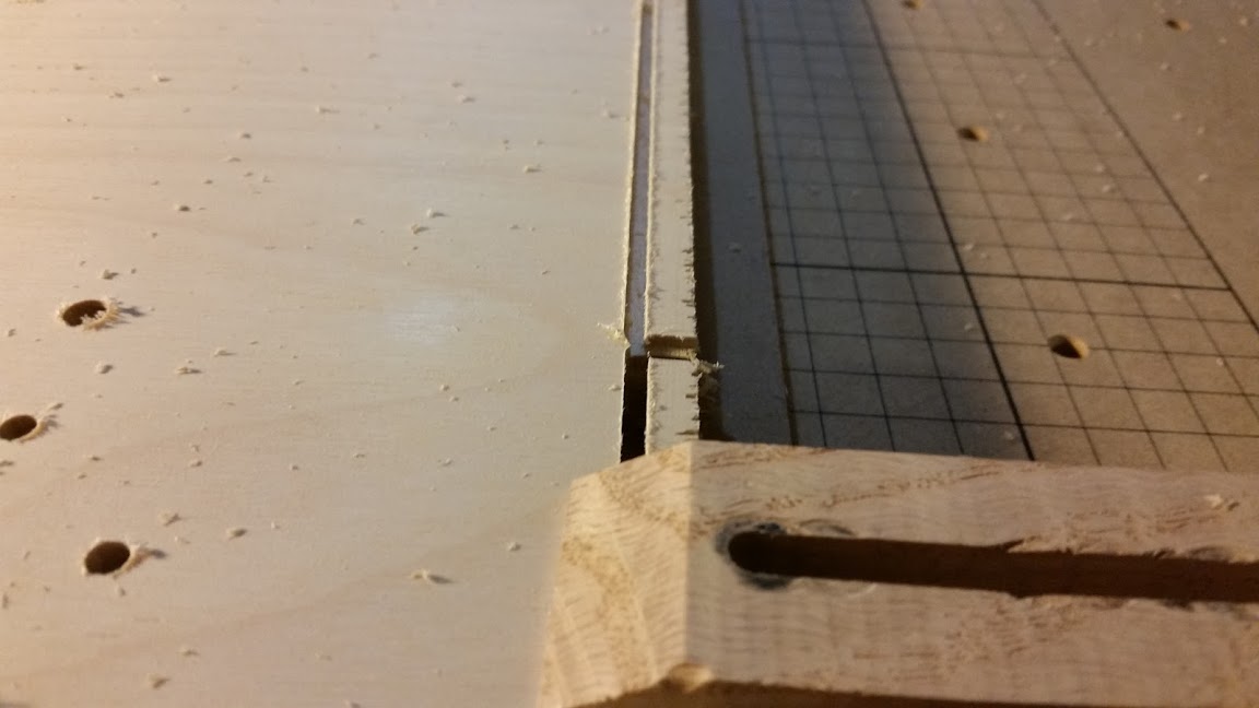
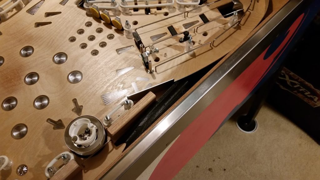
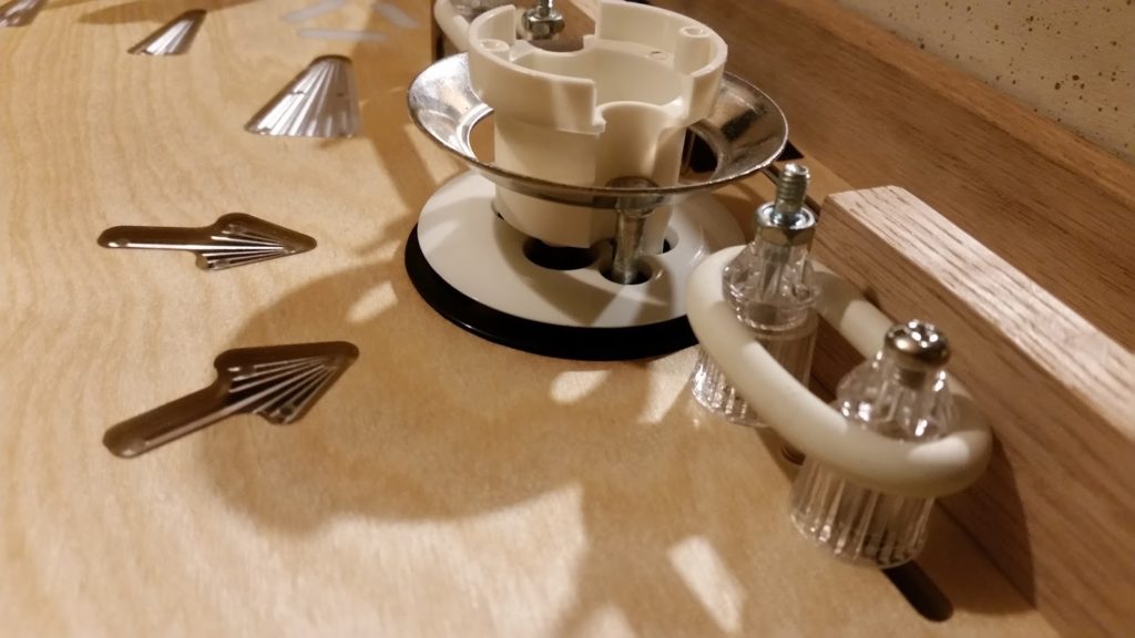
Deciding on the exact spinner placement.  This position won.

20160304_203925 (1)

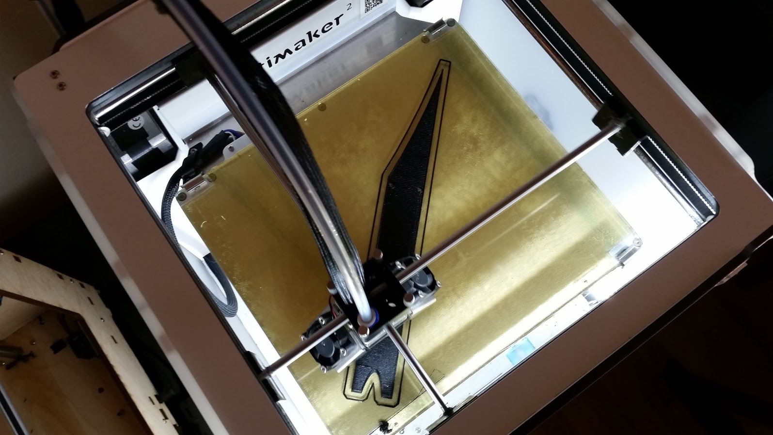
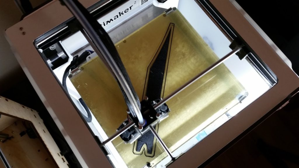
3D Printing the shooter lane skip ramp that allows the ball to enter the orbit on the right side.


20160305_130118

Hard to see, but the skip ramp is mounted and works great.

20160305_172327

More progress on populating and mounting some of the custom PCBs.

20160305_182751

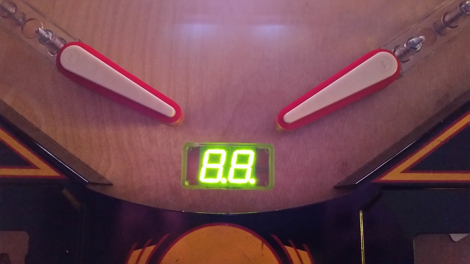
Assembled bonus LED PCB with PD-LED piggyback.  Very cool looking.

20160306_121524

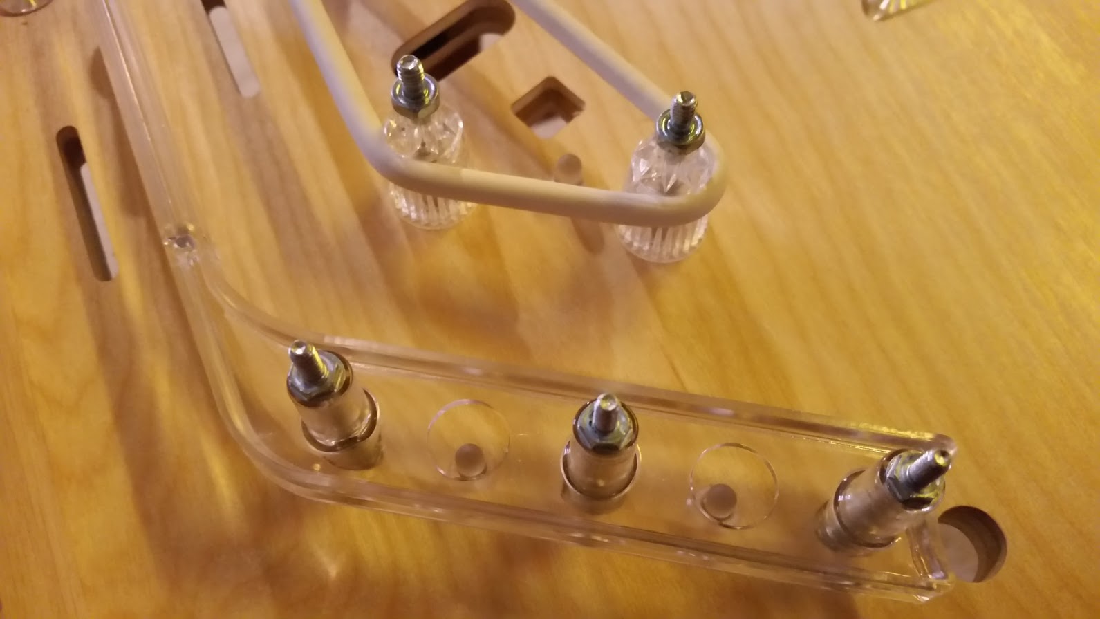
Here is that same board mounted between the slingshots.

20160306_122701

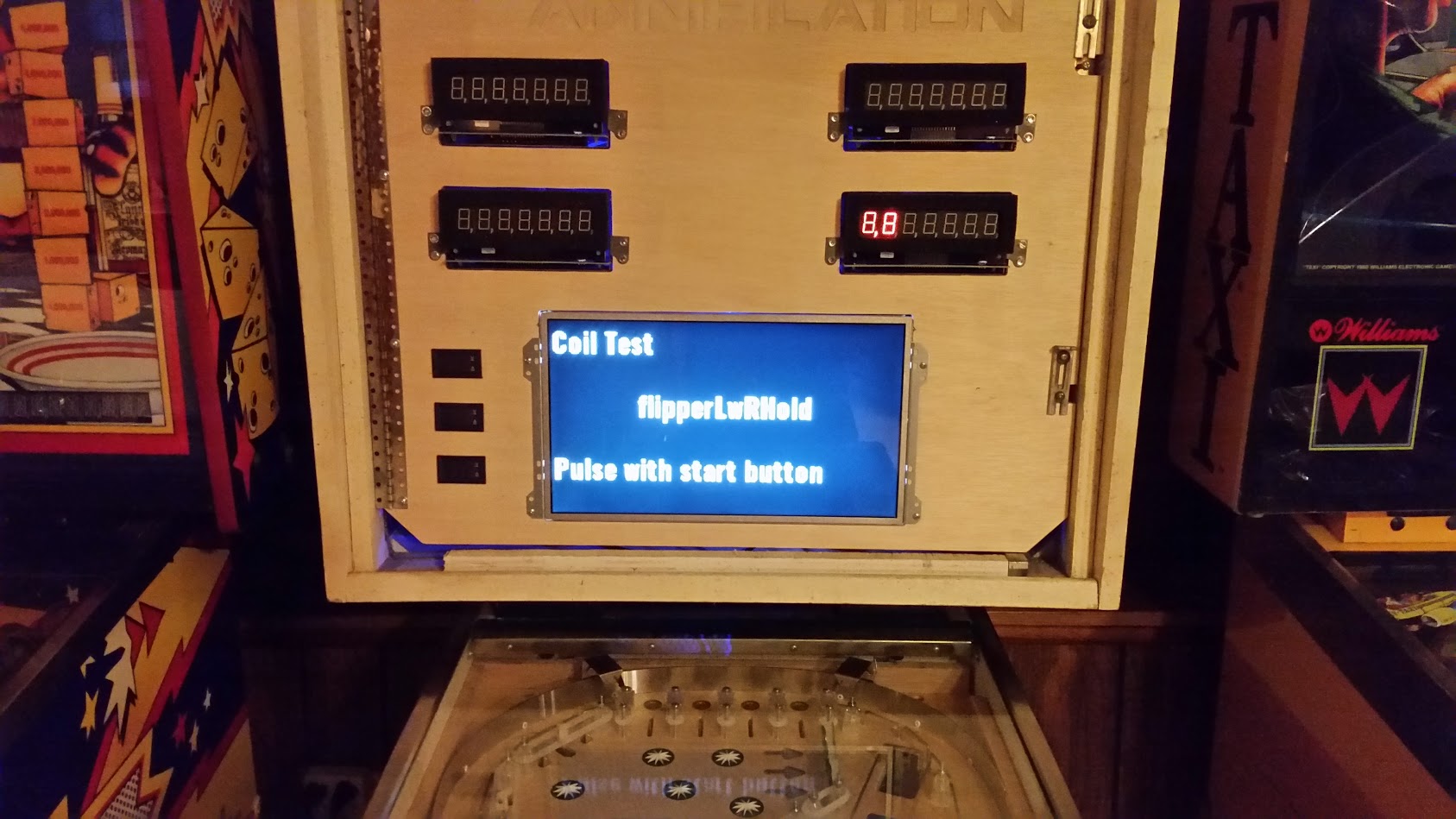
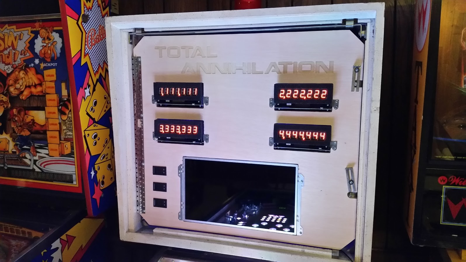
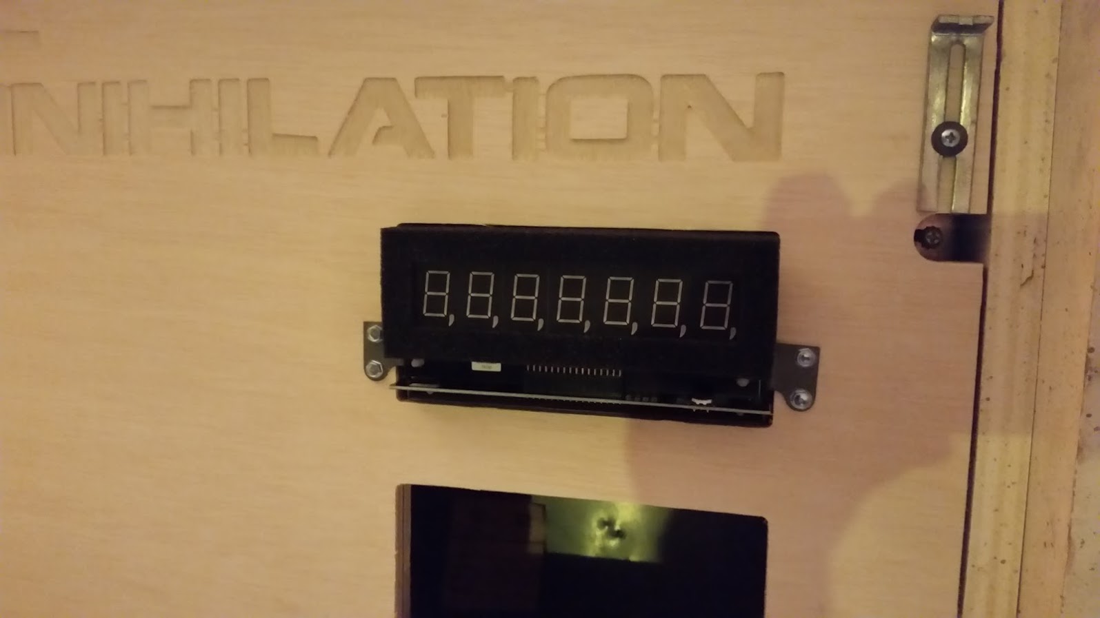
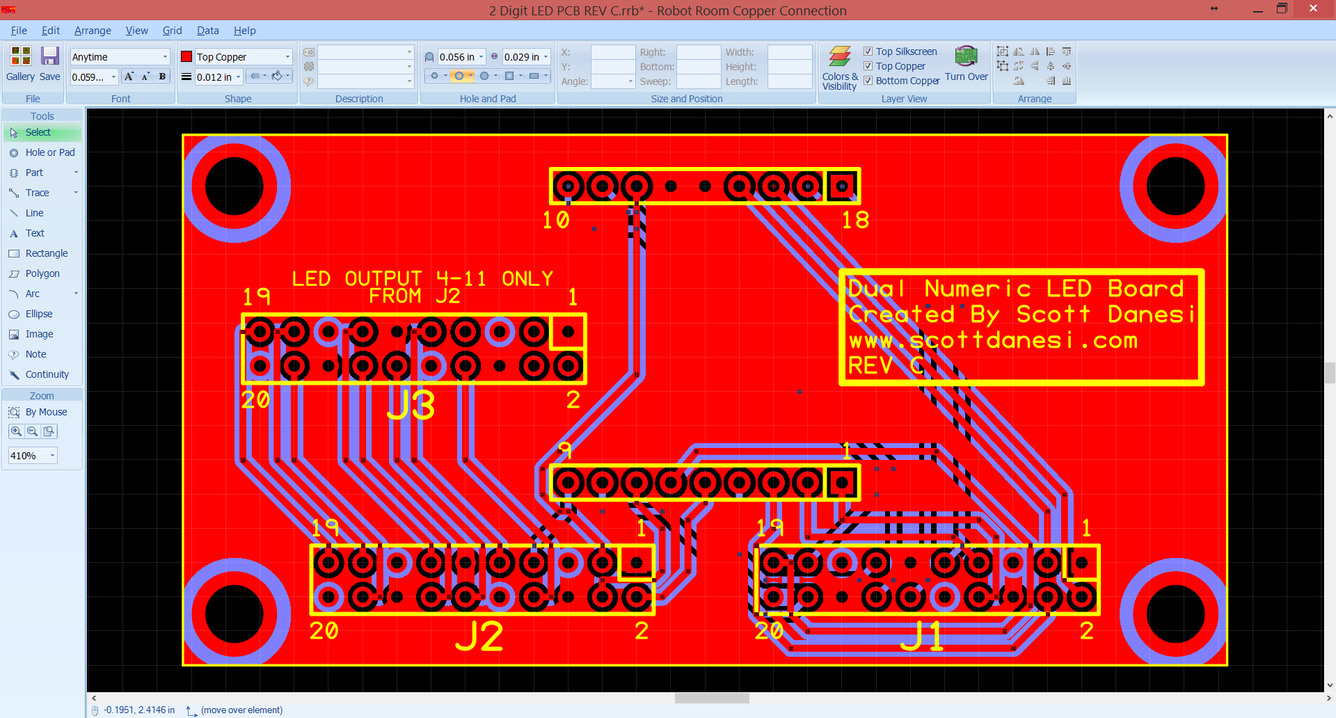
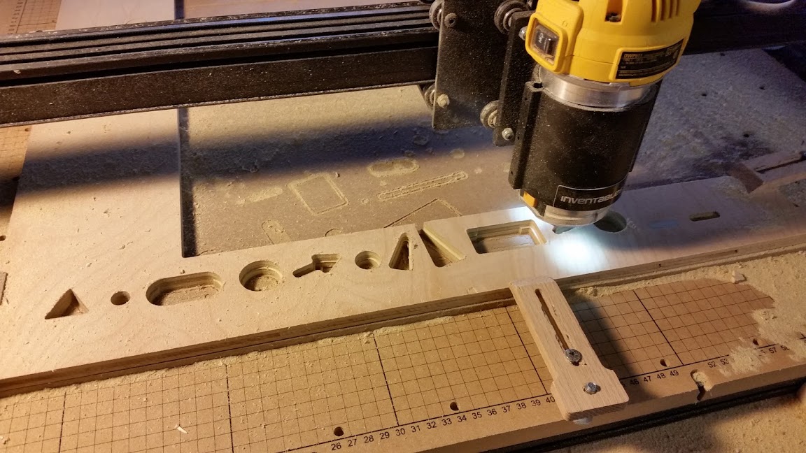
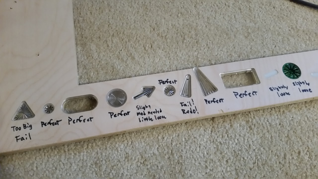
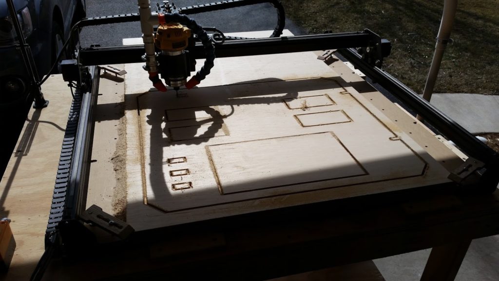
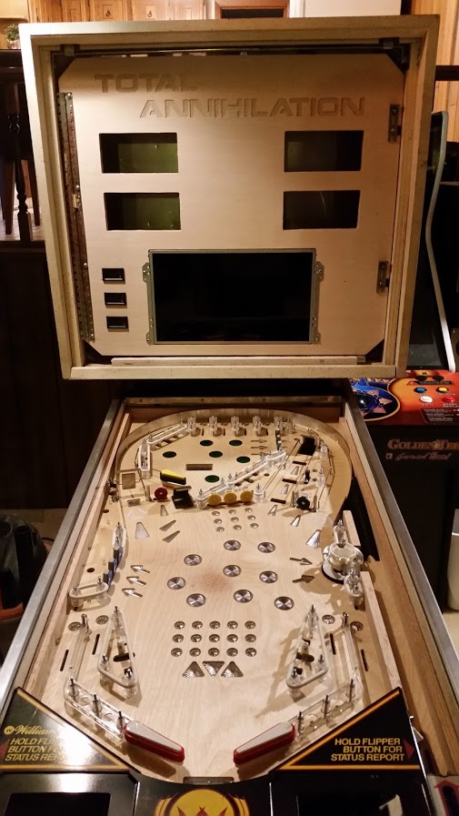
Every pinball machine from the 80’s needs a backglass insert panel.  I drew this one up to hold 4 LED numeric displays and my LCD.

20160306_124522

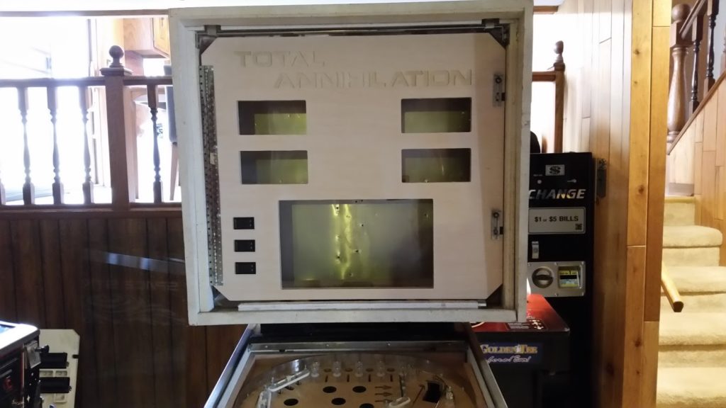
Here is a photo of the insert panel mounted in the backbox.

20160306_141305

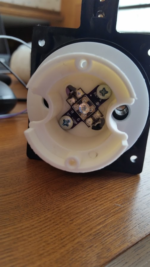
Just a close-up of my single pop bumper.  This is a DE style pop bumper with a black base.

20160307_190749

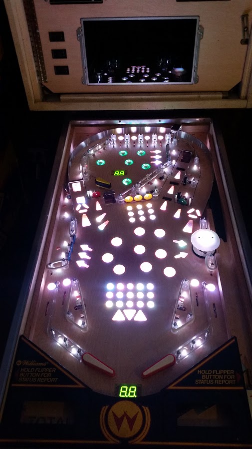
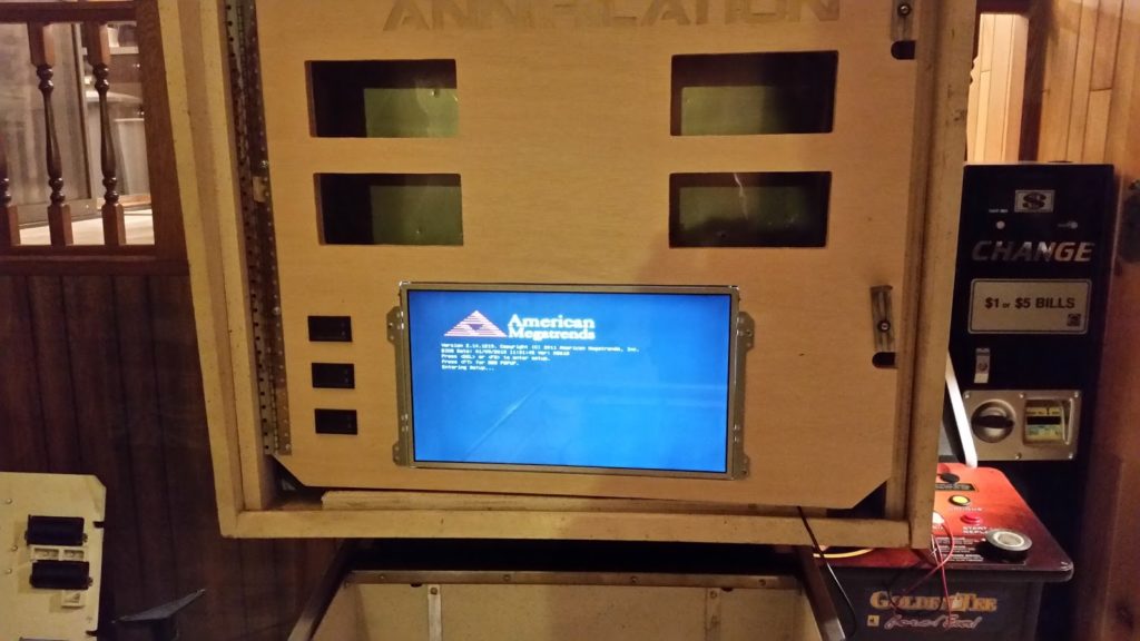
LCD has been mounted!

20160306_180702

Computer has been mounted and powered up…  Only problem is the computer that I was planning on using would not POST.  The motherboard ended up being toast, so I “recycled” it and used a Zotac C Series.

20160308_203855

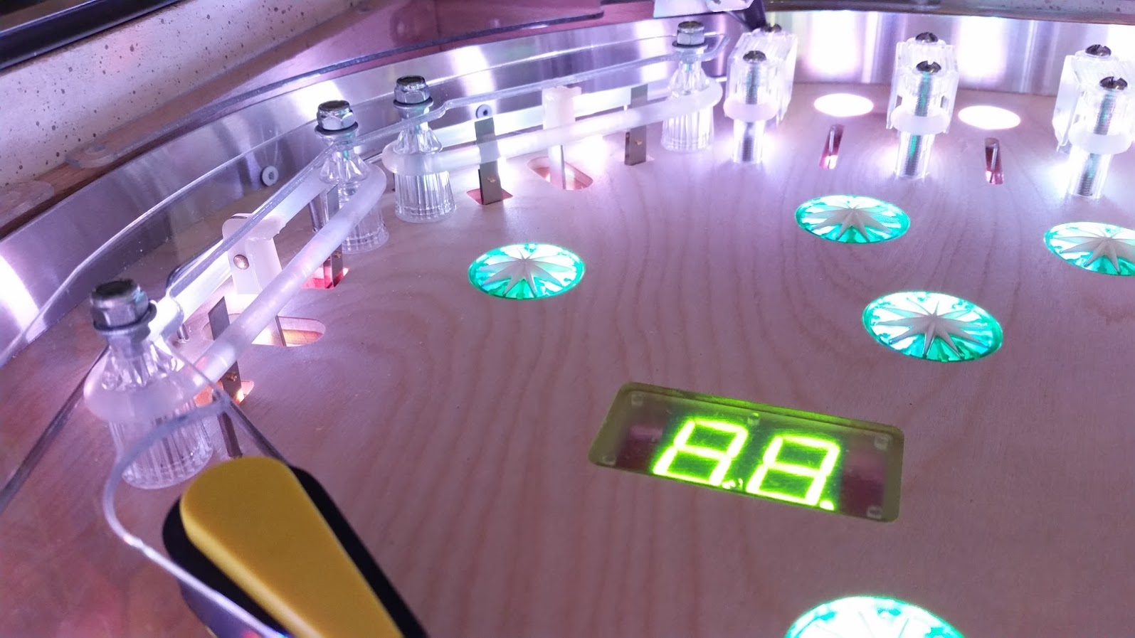
Test fitting the Bally LED displays.  They fit and look great!

20160316_175013

Diodes?  I have no need for you!

20160320_105327

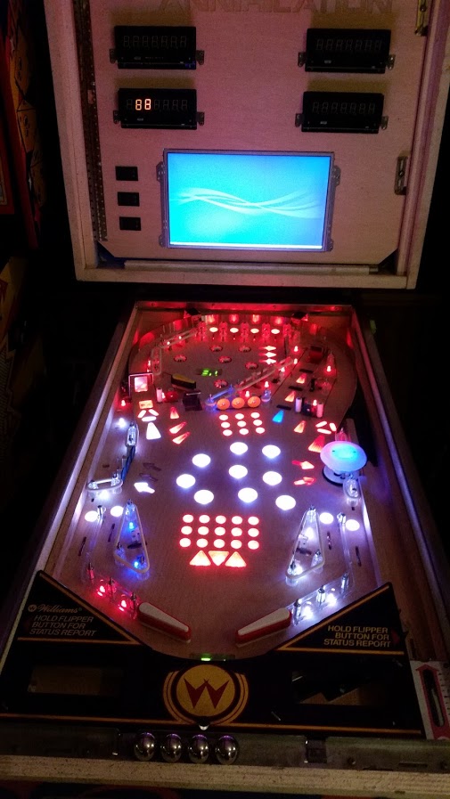
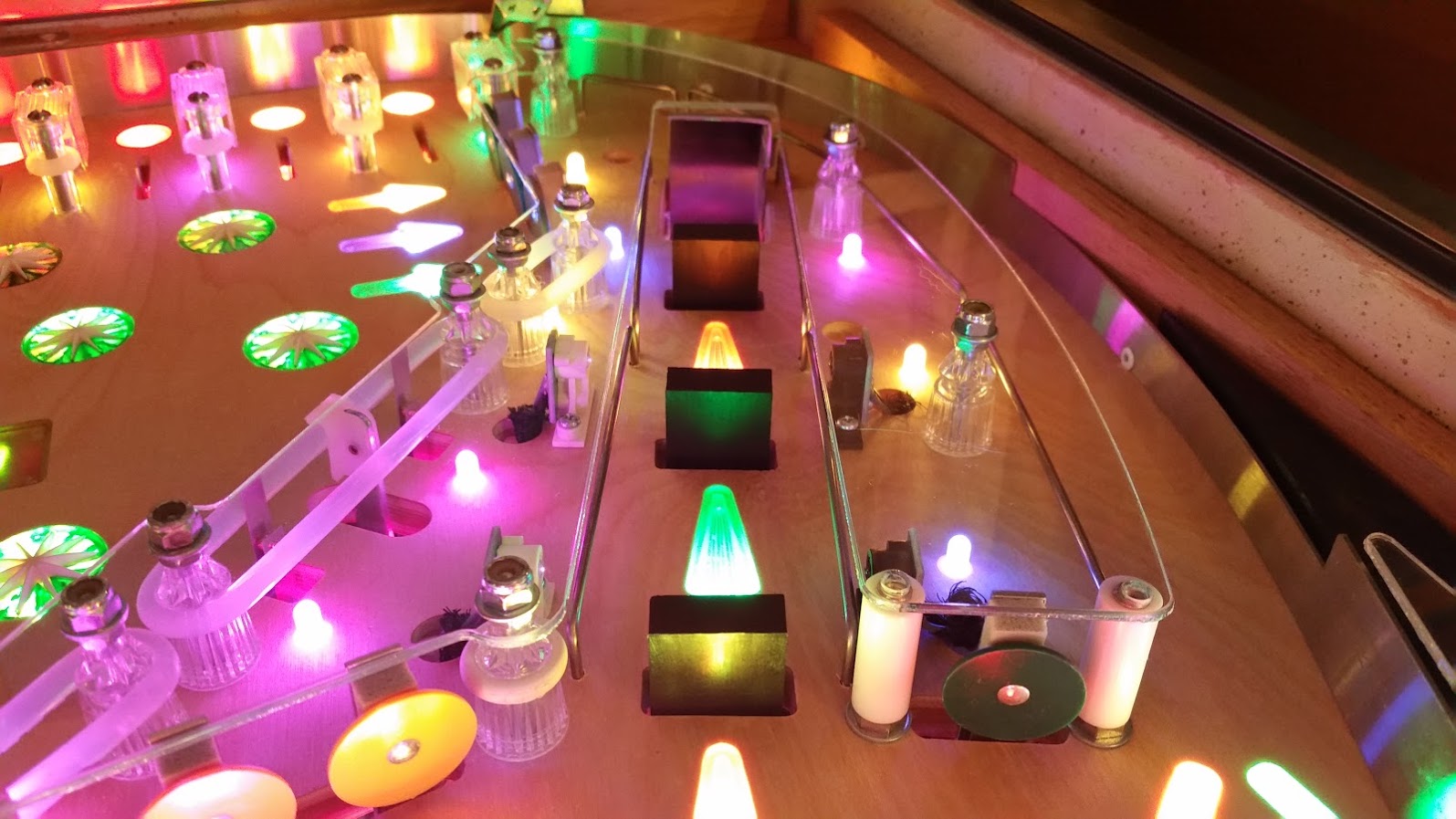
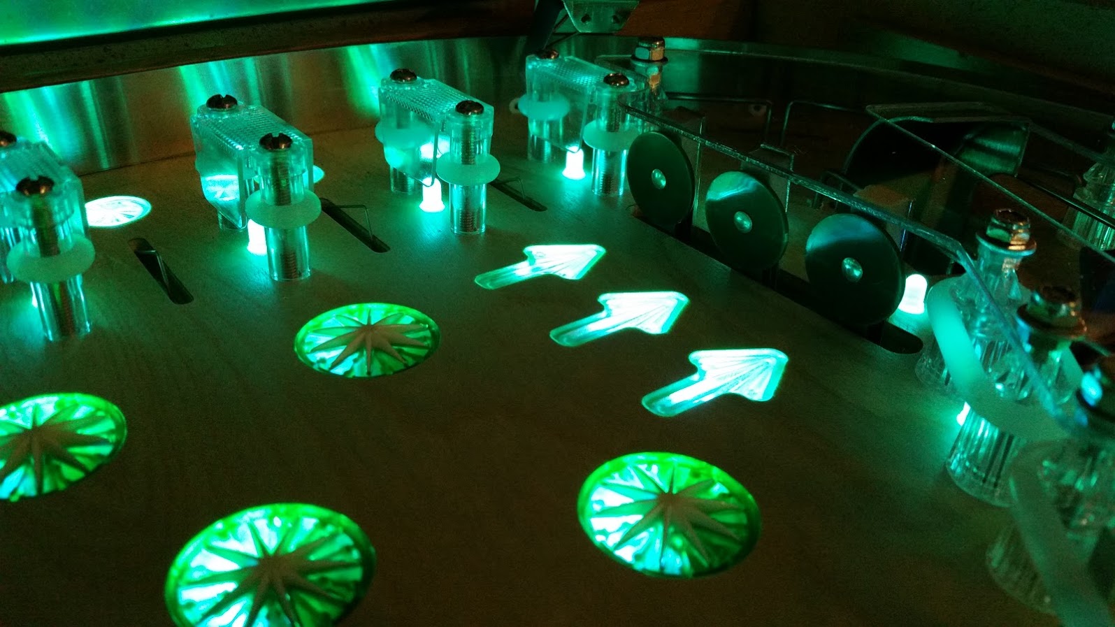
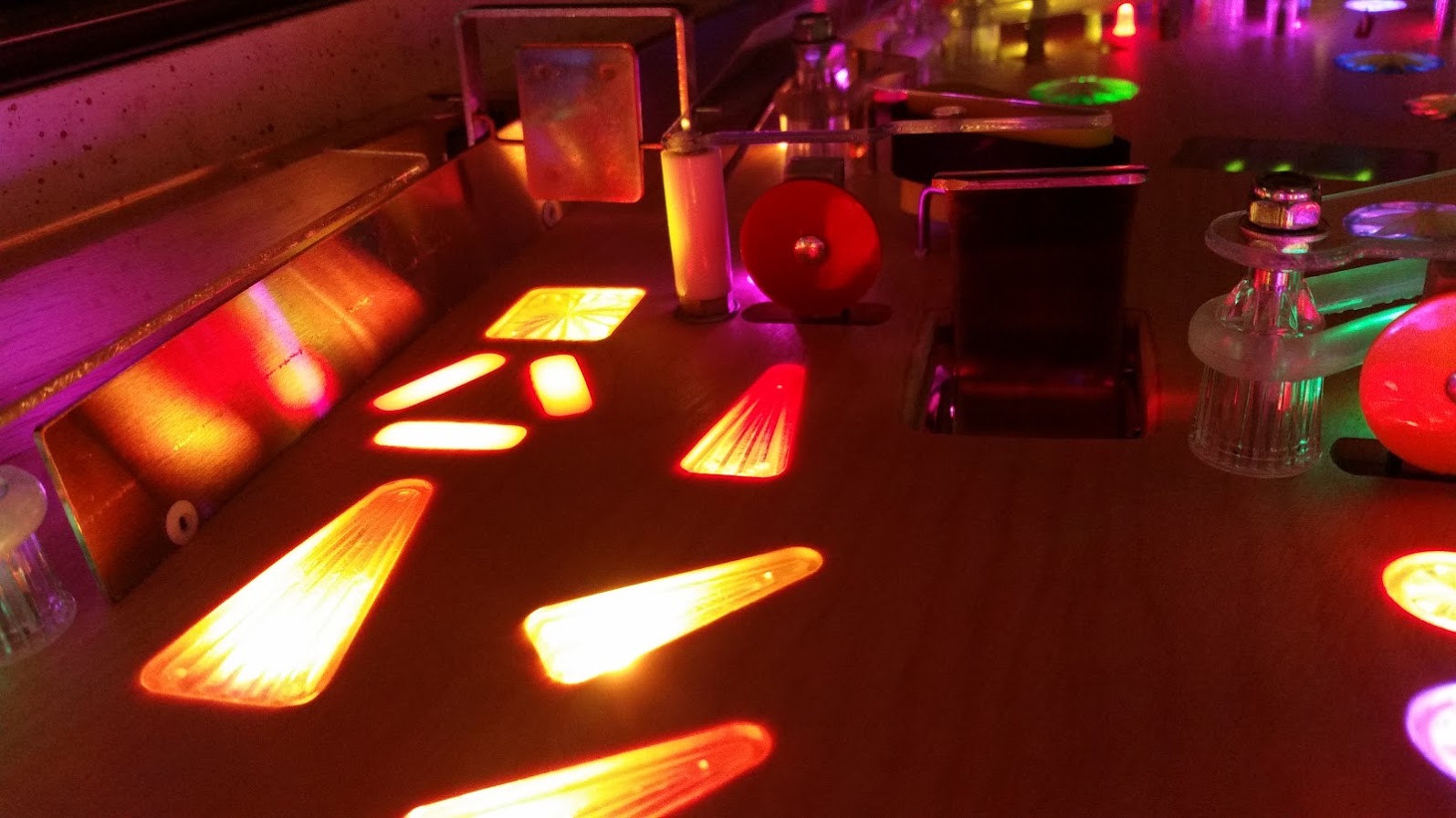
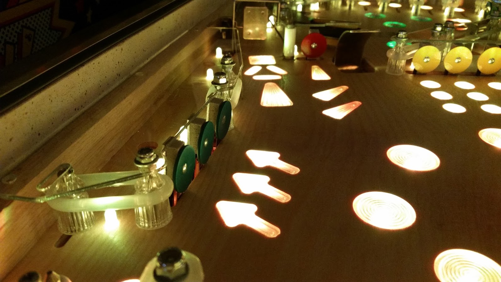
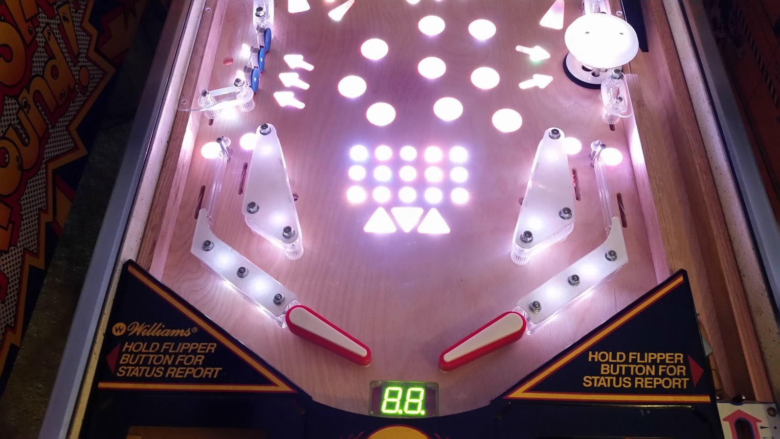
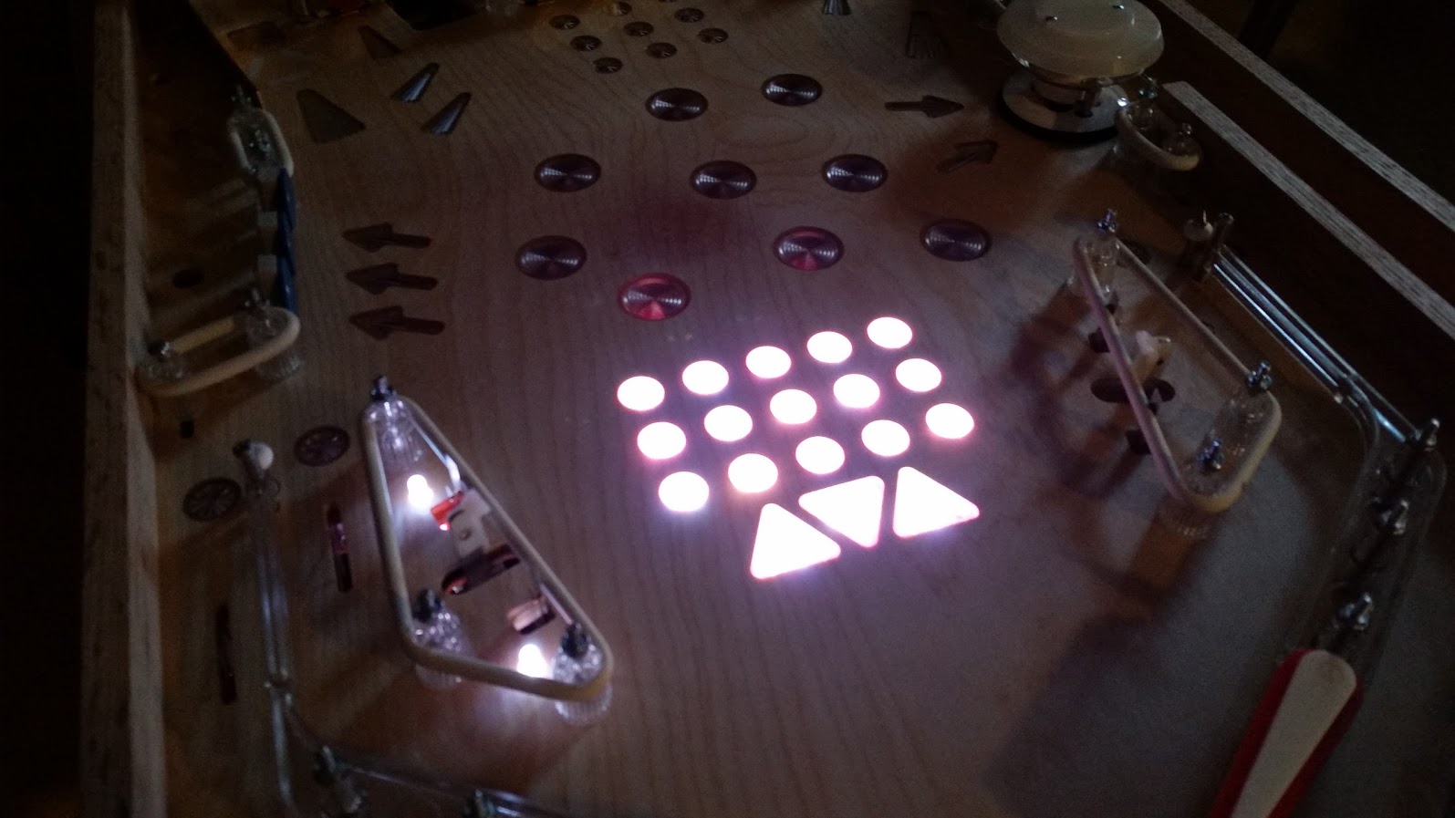
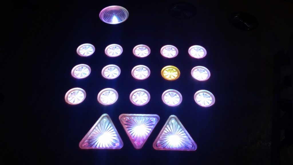
First boot of the PD-LED and the bonus LED assembly.  I also wired in 2 GI lights to the left just to try them out.  They ended up not being as bright as anticipated, but I compensated for that by putting them EVERYWHERE.

20160320_144341

There is always going to be issues when using bulk electronics.  In this case, I had the blue channel burn out on one of the Piranha LEDs.  All good though, they are cheap and I will be able to repair it easily.

20160320_180455

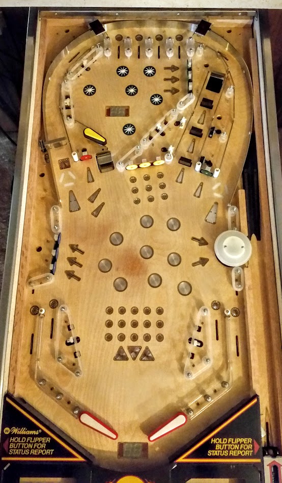
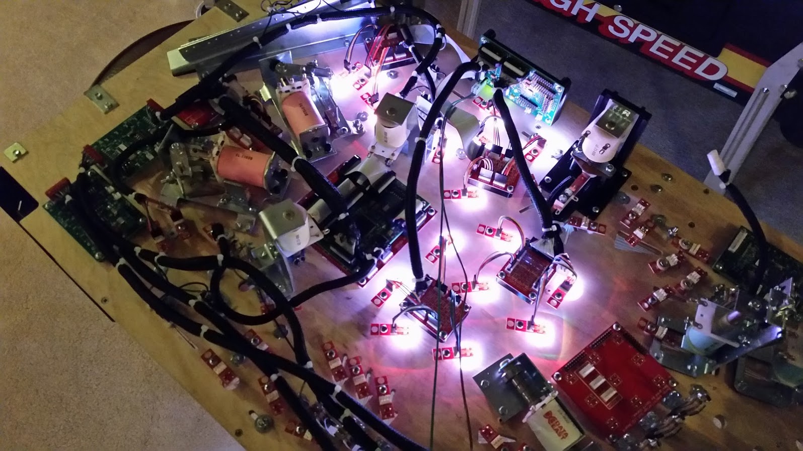
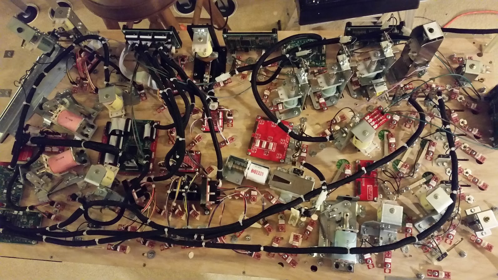
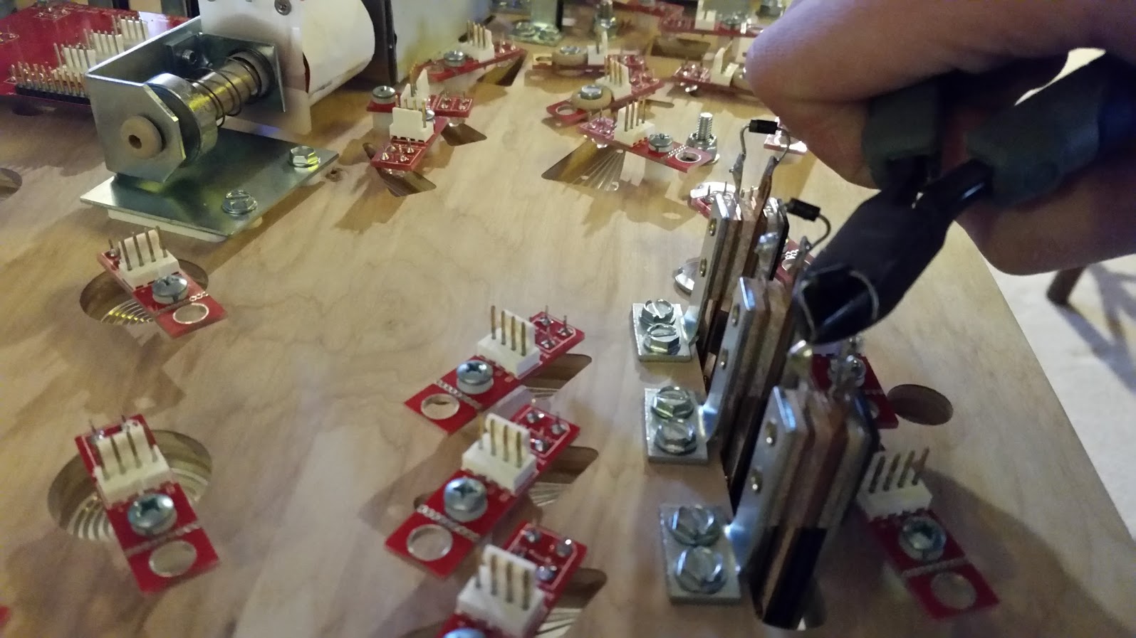
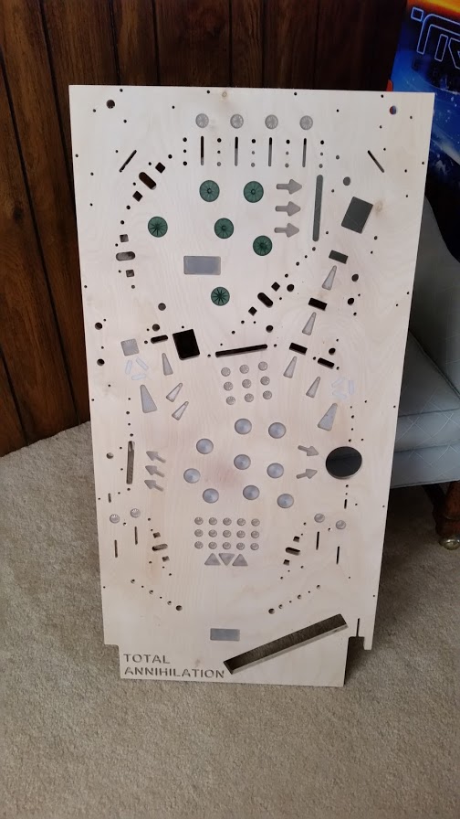
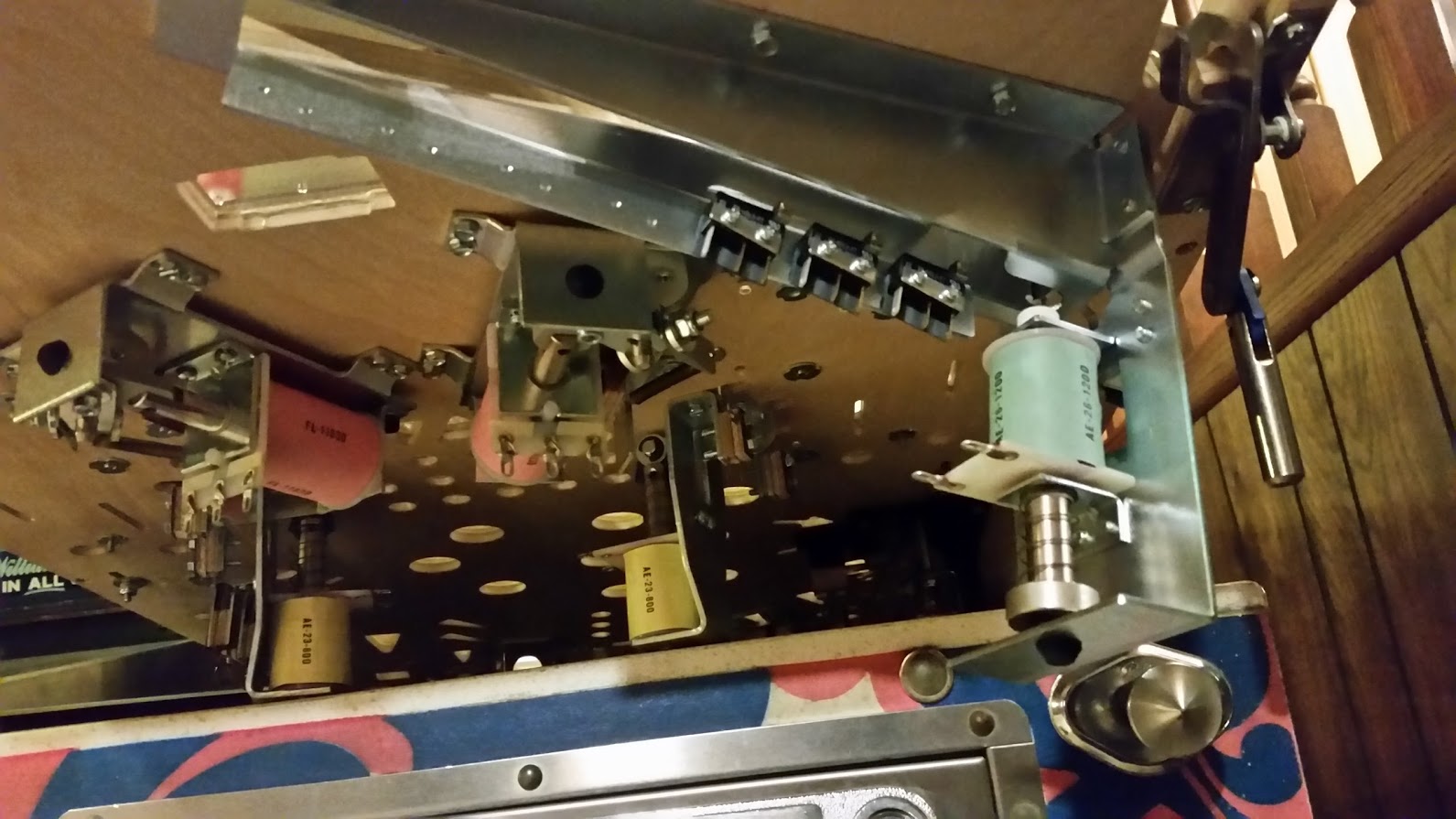
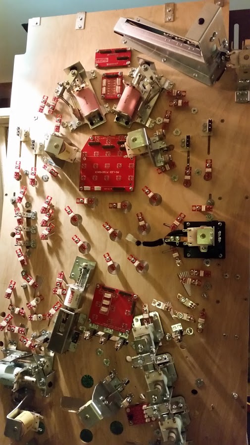
Now for the finale.  This is the latest picture of the bottom side of my playfield in full resolution.  I have successfully wired up 32 of my switches.  I have a bunch more, but will hammer through that pretty quickly.  I can then focus on getting all the LEDs wired up and do a full LED test.

20160320_180542

Hope you enjoyed the update.  Stay tuned for more.


Hey Everyone,

Long time since I last posted about the Total Nuclear Annihilation machine.  No worries, I am still working on it like crazy.  This update is going to be kinda fun since I took a bunch of pictures and screenshots along the way.

First off, the v3 playfield ended up having an issue where an inserts was way too large and I had to re-cut the entire thing as I did not notice it until after the playfield was done.  I quickly corrected the issue and started cutting v3.1!!!

20160131_154716

Version 3.1 of the TA playfield being cut

After this playfield was cut and I verified all was well with the inserts, I started populating them staring with the bonus multiplier triangles.  The glue that I used to secure these inserts is a clear 5 minute 2-part epoxy.  These inserts are in for life!


20160206_213907

Bonus multiplier inserts are in!

Below is a picture I took after I got ALL the inserts in place and hand sanded the playfield flat.  It was much more physical labor than anticipated…


20160213_124035

Sanded TA Playfield

Well after that, you can probably guess that I had to do an entire playfield swap from the v2 playfield that was sitting in my cabinet.  🙂

Here is a look at the playfield as it sat right after the main assembly swap!

20160214_170523

v3.1 playfield in!!!

For the GI, I ended up using light pipes that I will put VERY bright LEDs under.  My initial testing has shown that they spread the light very evenly.  These are similar to how TBL will be handling the GI in tight places.

20160214_121642

Light Pipes

I ended up designing a small RGB board that fits in the bottom of my pop bumper assembly.  These LEDs are bright as hell.  Check out the image below to see how it fits!

20160214_133515

RGB Pop Bumper

So here is the most important part to any playfield, the trough.  This is the new Pinball Life lower and upper trough.  I configured it for 4 balls.  This trough will be released by PBL very soon.

20160217_195529 (1)

PBL Upper Trough


PBL Lower Trough

PBL Lower Trough


PBL Trough Exit

PBL Trough Exit

Next on the agenda was getting some of the custom circuit boards designed and sent off for manufacturing.  Below are some screenshots of the boards prior to being sent off.

Custom RGB LED Board

Custom RGB LED Board


Custom PD-LED Breakout Board

Custom PD-LED Breakout Board


Custom 2 Digit Display Board

Custom 2 Digit Display Board


TA 3x3 RGB Lamp Board

TA 3×3 RGB Lamp Board


TA Bonus Lamp Board

TA Bonus Lamp Board


Well, that is all I have for now.  Hope you enjoyed the update!

Hey Everyone,

Just wanted to give a quick update on the V3 playfield.  I have finally finished the insert layout.  I decided to remove the obtuse arrows on the left side and sub in some nice early Bally style arrows.  I have also begin the process of testing out my insert hole machining.  The first test was actually pretty good.  Check out the results below.

PlayfieldV3Final

20160123_125951

20160123_130955

Hey Everyone,

Happy New Year!  Here is another update on the Total Nuclear Annihilation project.  I have currently finished populating and testing the layout of the V2 playfield.  The next step will be to finish the design of the V3 playfield that includes inserts.  I also need to update my trough cuts to adapt to the new Pinball Life ball trough that will be coming out early this year.  I will post some specs of that trough once I get it into my design.

Below are pictures of the populated V2 playfield, a video of my inline drop ball locking release, and a sneak peek at an early version of the V3 playfield that includes inserts.  Click on the images for the full size view.

20151227_112016

Playfield_Assembly_with_Inserts

Hey Everyone,

After populating my V1 playfield and testing a few things out, I discovered that my upper right kickback design was not very smooth and I just could not live with the design as it seemed amateur to me.  I ended up replacing the upper right side of the design with some straight inline drops with a scoop behind them.  I am going to do some really cool ball locking tricks with this setup and it will be much better than the original design.  Below is a rendering of the upper section of the V2 playfield that I updated.

A

So on a separate note, I have gotten a bunch of questions on how the hell I am milling a full sized playfield on an X-Carve that is only capable of doing 31″ x 31″.  The process is not that difficult.  Here are the high level steps that I perform to get my playfields cut.

Step 1: Export the full DXF file of my playfield from SolidWorks.  You will notice in the 2 images below there are 2 little lines sticking out of the right and left side of the playfield.  These will be referenced in the next few steps.

 21

Step 2: Import the full DXF into my CAM program and delete all the lines and artifacts ABOVE the 2 guide lines.  I then program the CAM and save as “Playfield Bottom”.

3

Step 3: Import the full DXF again to a new document and delete all the lines and artifacts BELOW the guide lines.  I then program the CAM and save as “Playfield Top”.

4

Step 4: It is important to make sure that the X (left/right) axis is the same for both the top and bottom playfield.  I ensure this happens by setting my X axis to the tip of the left guide line.  This will ensure that the left and right positioning of the 2 cuts are parallel.

Step 5: Start cutting the bottom part of the playfield and return the machine to X0 Y0 when complete.

5

Step 6: Once the bottom part of the playfield is cut, I unlock and slide the stock down and align the tip of the left guide line to the center of the end mill bit.  Once I am happy with the Y alignment, I lock the stock back in place.  I then proceed to cut the top part of the playfield without resetting my X or Y axis in the software.  The machine will pick up where it left off and hopefully continue like it was all cut at once.  It is not perfect every single time, but it is damn close.

6 7

Step 7: Let the machine continue and do not set your beer by the Emergency Stop button.