
Hey Everyone,
It’s been a while, but I promise you a great update. I have been making a large amount of progress on the playfield wiring and other various items on the checklists. Check out the progress below!
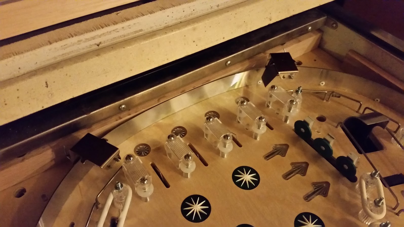
I finally got both of my controlled gates built and installed! These are using coils under the playfield to pull them up as needed. This will be a very cool feature of the game which will allow me to open the orbits on the fly.
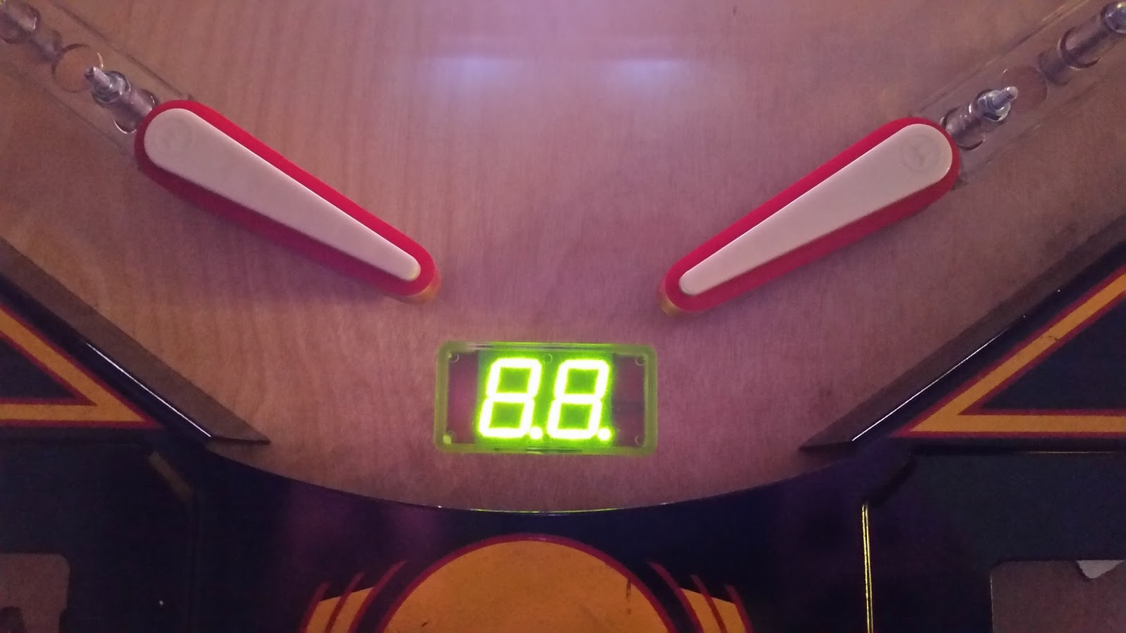
My LED segments are alive! These are really cool looking in person. I will be able to display ball save countdown seconds along with linking them to my lamp shows to do some really cool stuff.
Making progress on the wiring of the breakout boards and the RGB LED boards.
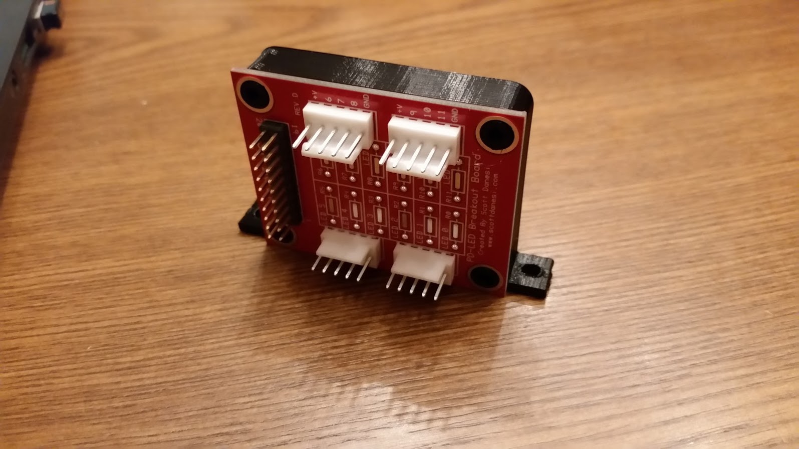
Here is a closeup of one of my RGB breakout boards. This connects directly to the PD-LED and then has headers to connect to the RGB LED boards. Pretty handy little PCB.
More progress on the wiring. You can see I am starting to run the switch harnesses from the switches to the SW16 boards just off the left side of the image.
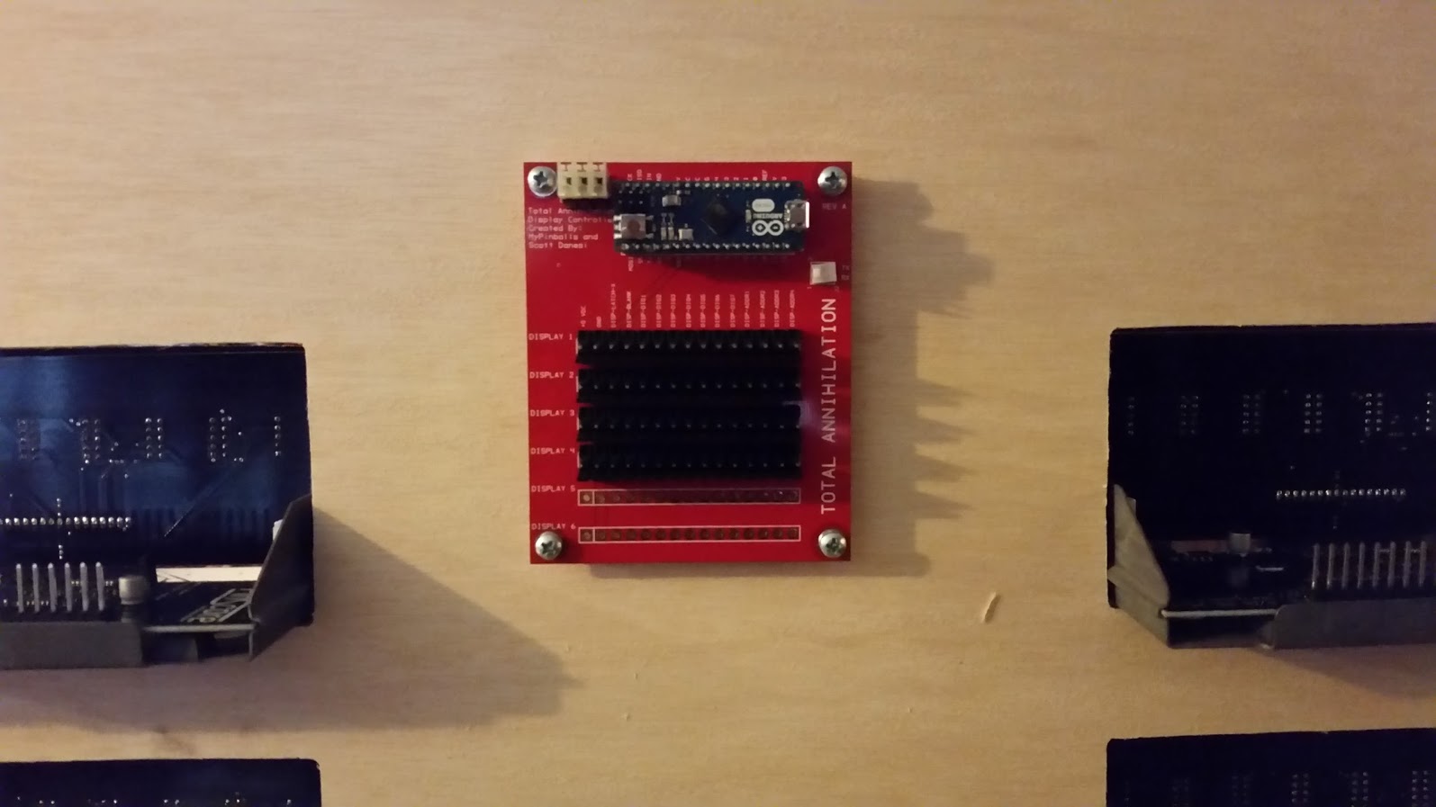
OK, it is starting to get really crazy here. This PCB is a custom shield that houses an Arduino Nano that will control my 4 numeric Bally displays.
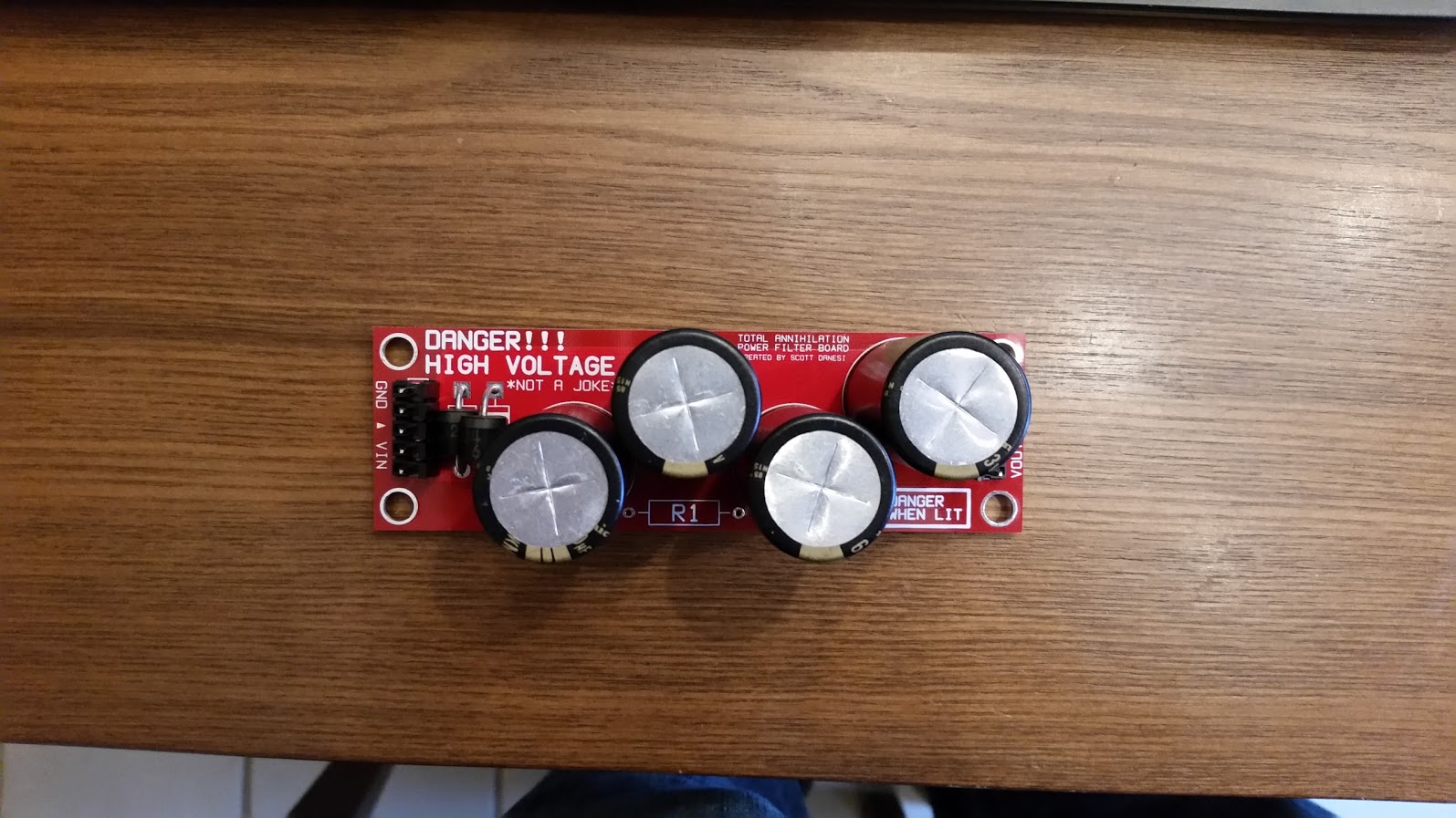
This board below is a pretty dangerous one… This is my 48v filter board. Basically, it will smooth out the 48v dips when coils fire by charging up these large capacitors and pulling a large amount of current quickly from them instead of all from the power supply directly. This will also make my 48v line in my machine more dangerous since these capacitors can discharge a large amount of current very quickly into, let’s say, my hand. 😐
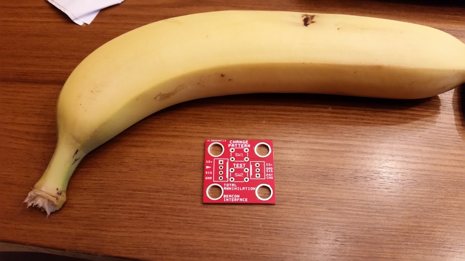
This is one of the smallest custom PCBs that I have built for this project. This is an interface board for the emergency beacon that lives on top of my backbox. It allows me to test and to change the pre-programmed patterns without the game running. Obviously, a banana for scale…
Ok, here is where it starts getting pretty cool in the display department… These displays in the picture are being controlled by the Arduino Nano using some code written by Mr. Jim Askey of MyPinballs.com. These are now ready to go!
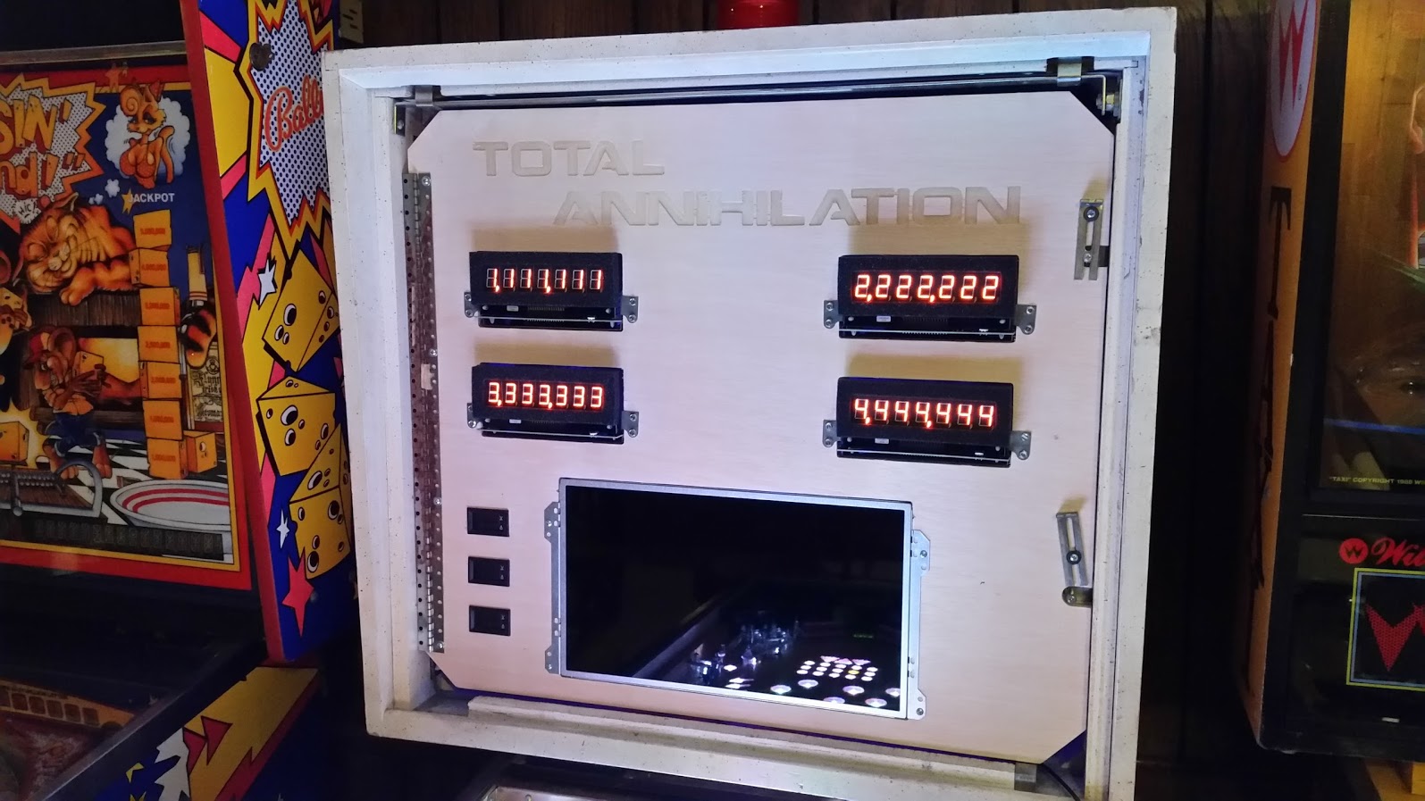
Of course, I could not leave the code as it was. I created a very cool little startup test sequence that will show up upon initial boot. Video below.
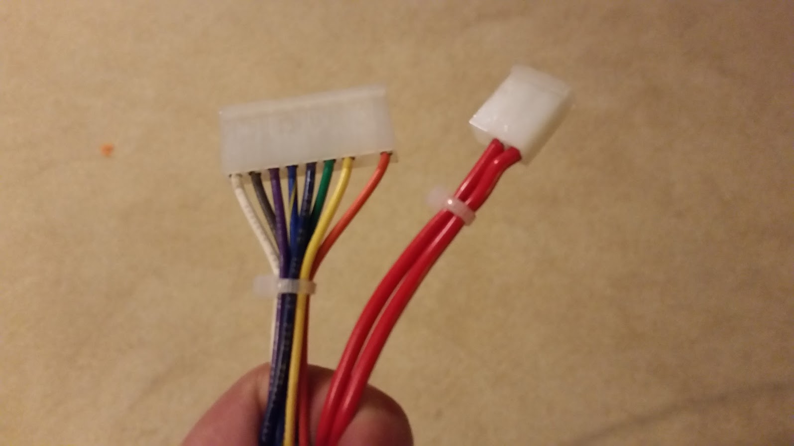
I have been covering most of my wires with black wire wrap to keep it clean, but these are just too good looking to cover up. These are the plugs that lead to one of the banks of coils on my playfield.
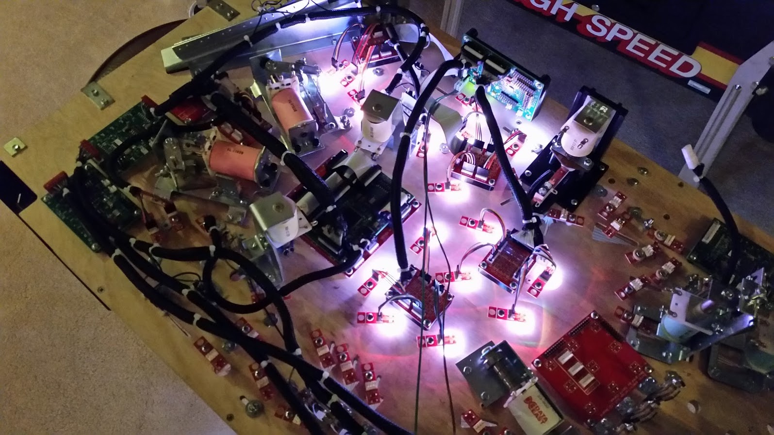
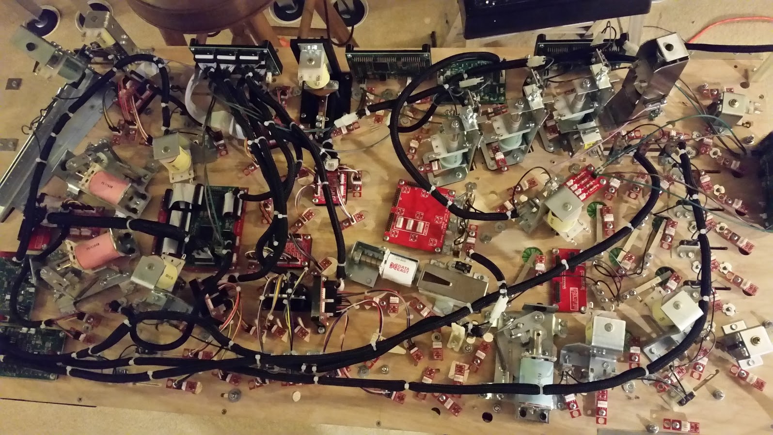
And for the final pictures of the update… You guys aren’t going to believe this, but I successfully completed all the under playfield wiring. This includes all serial connections, power connections, switches, coils, and lamps. I am pretty much done under there. Now onto the cabinet!
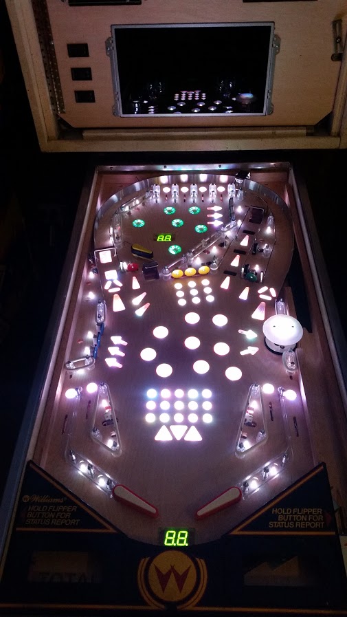
Here is a picture of the playfield with all the inserts lit up at full power!
And finally, below is a full res picture of the bottom of my playfield. Feel free to inspect away! 🙂

Hope you enjoyed the update, until next time!
