
Hey Everyone, it has been a long time since I did an actual pinball related blog post, so here it is! I have been getting a ton of questions lately on how to properly power opto transmitter LEDs and how to hook up the receivers to the SW-16 P-ROC boards. I am going to walk through it in enough detail that you should be able to get up running on the concepts quickly.
Powering Opto Transmitters
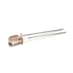 Opto transmitters are nothing more than high powered infrared LEDs. For this guide, I am going to be referring to the Williams/Bally style opto transmitter which can be seen here: https://www.pinballlife.com/williamsbally-led-transmitter-emitter-for-opto-assemblies.html. This LED emitter has no circuitry attached to it by default. These LED emitters are also used on the small PCB and bracket assemblies seen here: https://www.pinballlife.com/williamsbally-led-transmitter-emitter-and-pcb-board.html and other various trough board assemblies.
In order to safely power this LED, you will need to gather a few data points and make a couple small decisions. You will need to know the forward voltage of the LED, maximum constant current that the LED can handle, decide what input voltage you would like to supply to it (5v or 12v), and decide how much current you would like to give the LED to ensure it has enough power to transmit infrared light to reach your opto receiver.
So here is our data:
- Forward Voltage: 1.7v
- Max Constant Current: 100ma, but I recommend you do not exceed 75ma to maximize the life of the LED. This will be powerful enough to transmit a pretty decent amount of distance between the emitter and receiver.
- Input Source Voltage: 5vdc is my recommendation as it is higher than the forward voltage of the LED, and low enough that the resistor does not have to dissipate too much heat.
These LED emitters will need a current limiting resistor in series with them as applying 5v or 12v directly to the LED will cause it to overload and fail. Now, to calculate this resistor value, we will need to calculate resistance and power based on the data that we have. Now, I could be idealistic and talk about the actual calculations, but I am going to show you how I usually calculate this using an online LED resistor calculator. The one that I use the most is the one below. I have already filled out the fields, but feel free to change some of the values up to see what happens.
http://led.linear1.org/1led.wiz?VS=5;VF=1.7;ID=75
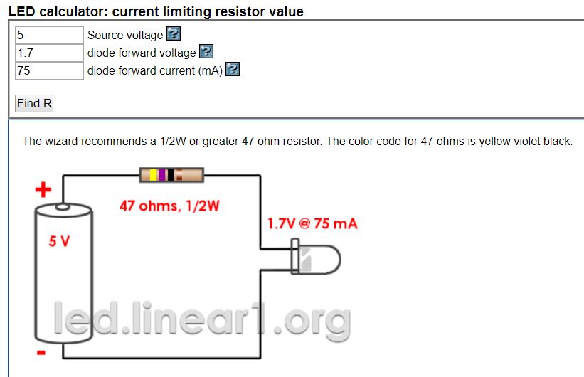
So as you can see above, the calculator has automatically figured out what the ohms and recommended resistor wattage should be for our emitter. What I also like about this calculator is that it gives a nice visual representation of how to wire the circuit and what the resistor color bands are.
Important note: Please be sure to use at least the recommended resistor wattage. You can see above that the calculator is recommending at least a 1/2 watt resistor. Too small of a resistor and it can burn up, which is bad. 🙂
That is about it for powering an opto emitter!
Connecting Opto Receivers to the SW-16 P-ROC Board
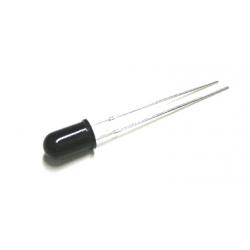 Now for this section, I am going to be talking about the Williams/Bally style opto receivers and how they hook up to the SW-16 P-ROC switch boards. These are the black colored opto receivers that can be fond here: https://www.pinballlife.com/williamsbally-led-receiver-for-opto-assemblies.html. These, just like the emitters, are also used in small PCB assemblies, and trough opto boards as well.
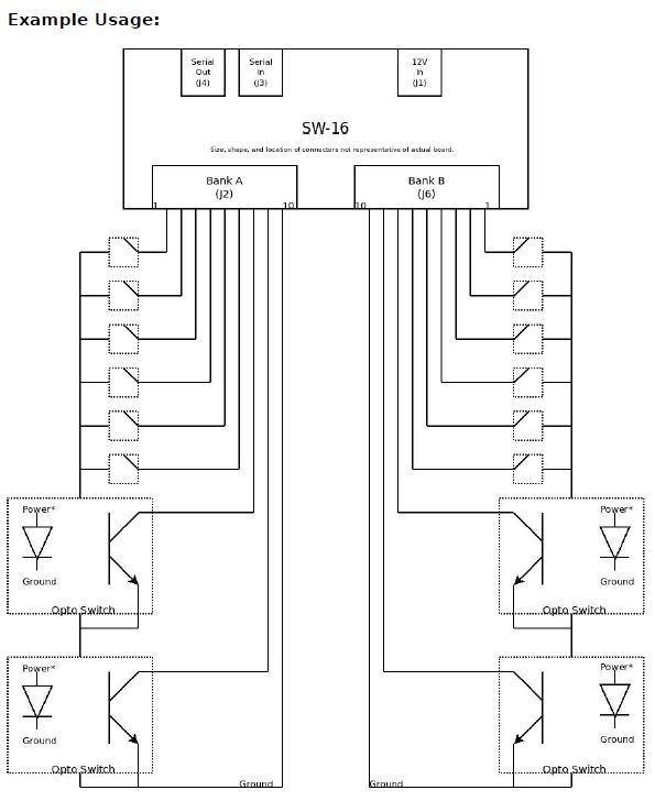
To connect these optos into the SW-16 P-ROC board, you will simply need to wire it directly to the inputs of your switch board. It is really that easy. It will act just like a standard switch as long as it is connected in the correct orientation. Below, you will see an image from the P-ROC documentation. The cathode/ground side of this diode is the side with the flat indentation on the black epoxy base of the opto. Please also keep in mind that opto receivers are normally closed switches and when it detects the IR beam from the emitter, it will open. This is opposite of a normal switch. When a ball breaks the opto beam it will go from a closed state to an open state.
The full documentation can be found here: https://www.multimorphic.com/content/uploads/2017/07/SW-16-2_LLD_v2-0.pdf
I hope this all makes sense and helps you get your project up and running! Please also keep in mind that some Stern and certain Williams trough boards have resistors built into them on the emitter side. The guide above will allow you to connect to boards and directly to emitters that have no circuit logic.

Great info, Scott! Are the otpotransmitter and receiver the same ones used on the pinballlife scoop assemblies as well? It also might be helpful to add marking information for those assemblies (i.e. connection back from the schematics drawn to the E, C, A, and K on the assemblies). The first side I saw was A/K and I got confused what it was actually looking for. I’m just used to silk screen lines indicating cathode and I think others might be confused as well.
But great info! I found this with a google search and I didn’t realize you had some of this design information on your site as well. I’ll have to look around more. Thanks!
Thanks Scott, this is very helpful!
The only question I have is how would you wire multiple optos?
Say your pin had a total of 6 optos, would you connect them in parallel using a 5v supply (6 resistors in total), or in series with a 12v supply (1 resistor)?
I used the LED series/parallel calculator to find the resistor values for each scenario, I’m just wondering whether one is preferable over the other?
Hey Aaron,
For this, you would have 1 resistor per opto. You can use some online calculators to run multiple optos from 1 resistor, but that is just a design choice, but just be sure your resistor can handle the wattage that is required. 🙂 Hope that answers your question. Thank you,
–Scott