How To

Hey Everyone,

I know this is not the most exciting post about new pinball stuff, but I just wanted to share this code with the world that I created to get around a huge limitation in Oracle NetSuite.

We recently upgraded our backend system to NetSuite Manufacturing and it has been really great so far. I am a huge data nerd as many of you know. The one major issue we have been having is trying to get a nice report of the Bill of Material (BOM) components within our Assemblies with the current and average costs. We use these reports to make sure that we are not under or overcharging for parts that we assemble in house. After looking around online and talking to support, it was clear there was no solution to show this properly. You can see what the last build price is, but that is not what we need. So I took it upon myself to write a direct SQL query into the database to show what we need. I feel that this is so valuable for the community that I wanted to post it up here as a starting point for others.

In order to run direct SQL in NetSuite, you will need to first install the free SuiteQL Query Tool from Tim Dietrich from the link below:

https://timdietrich.me/netsuite-suitescripts/suiteql-query-tool/

Once you install and configure this script within your NetSuite environment, you will need to copy the code below into the query window. Once you have that code ready to go, you will need to update 2 places in the code that reference the BOM Revision name. You must copy the BOM Revision name from your system exactly for this to work. Once the 2 spots are updated, you can hit run and enjoy the BOM analysis!

/********************************************************************************
Title:			Pinball Life NetSuite Assembly Cost Analysis SuiteQL Query

Created: 		2023-03-22 (Scott Danesi)

Description: 	Basic BOM Revision costing report used to show average cost 
				analysis on specific BOM Revisions in NetSuite.

Instructions:	Replace the 2 revision names in the code below to the
				exact revision name that you would like to run the report for.
				These revision names must be the full revision name.  If both
				revision locations are not replaced, the report will give
				incorrect results.
********************************************************************************/

SELECT
	t2.fullname as "assembly name",
	t2.displayName as "assembly description",
	bomRevision.name as "bom revision",
	item.itemId as "component Name",
	BomRevisionComponent.description as "description",
	BomRevisionComponent.bomQuantity as "quantity",
	to_char( item.cost, '$9,999.9999' ) as "cost",
	to_char( CASE WHEN item.averageCost = 0 THEN item.cost ELSE item.averageCost END, '$9,999.9999' ) as "average cost",
	to_char( BomRevisionComponent.bomQuantity * CASE WHEN item.averageCost = 0 THEN item.cost ELSE item.averageCost END, '$9,999.9999' ) as "avg cost total",
	to_char( CASE WHEN item.lastPurchasePrice = 0 THEN item.cost ELSE item.averageCost END, '$9,999.9999' ) as "last purchase price",
	to_char( BomRevisionComponent.bomQuantity * CASE WHEN item.lastPurchasePrice = 0 THEN item.cost ELSE item.averageCost END, '$9,999.9999' ) as "last purchase total",
	t1.altName  as "preferred vendor" 
FROM
	BomRevisionComponent
	LEFT JOIN item ON BomRevisionComponent.item = item.id
	LEFT JOIN bomRevision ON BomRevisionComponent.bomrevision = bomRevision.id
	LEFT JOIN
		(
			SELECT
				itemVendor.item,
				itemVendor.preferredVendor,
				itemVendor.vendor,
				Vendor.altname
			FROM
				itemVendor
				LEFT JOIN Vendor ON itemVendor.vendor = Vendor.id
			WHERE
				itemVendor.preferredVendor = 'T'
		) as t1
		ON t1.item = item.id
	LEFT JOIN 
		(
			SELECT
				item.fullName,
				item.displayName,
				item.id,
				bomRevision.name
			FROM
				item
				JOIN bomAssembly ON item.id = bomAssembly.assembly
				JOIN bom ON bomAssembly.billofmaterials = bom.id
				JOIN bomRevision ON bomRevision.billofmaterials = bom.id
		) as t2
		ON t2.name = bomRevision.name
WHERE bomRevision .name = '0199-0699_LEFT-BOM-REV-' 			/************ <--- Change this to the exact BOM Revision that you want to see. ******************/

UNION

SELECT
	NULL as "assembly name",
	NULL as "assembly description",
	NULL as "bom revision",
	NULL as "component name",
	'TOTAL COST' as "description",
	NULL  as "quantity",
	NULL  as "cost",
	NULL  as "average cost",
	to_char( SUM(BomRevisionComponent.bomQuantity * CASE WHEN item.averageCost = 0 THEN item.cost ELSE item.averageCost END), '$9,999.99' ) as "avg cost total",
	NULL as "last Purchase Price",
	to_char( SUM(BomRevisionComponent.bomQuantity * CASE WHEN item.lastPurchasePrice = 0 THEN item.cost ELSE item.averageCost END), '$9,999.99' ) as "last purchase total",
	NULL as "preferred vendor" 
FROM
	BomRevisionComponent
LEFT JOIN item ON BomRevisionComponent.item = item.id
LEFT JOIN bomRevision ON BomRevisionComponent.bomrevision = bomRevision.id
WHERE bomRevision .name = '0199-0699_LEFT-BOM-REV-'			/************ <--- Change this to the exact BOM Revision that you want to see. ******************/

Please keep in mind, this is the first revision of this code that I made, it is not the most efficient or the cleanest, but it is a good starting point if you need to see this data. I really hope this helps someone out there as much as it did for me. Please feel free to reach out to me if you have any suggestions, or see any errors in my code. Enjoy!

I get this question pretty frequently, so I figured I would post a how to guide on getting the most out of the audio system on your Total Nuclear Annihilation pinball machine.

Do this at your own risk as this has the potential to damage your amp and/or speakers if set too high. But please do not do this unless your amp settings get totally out of whack.

Warning, this setup procedure is going to be loud, so warn the people around you.

Subwoofer Physical Adjustment (do this first):

You may notice some strange distortion coming from the subwoofer… These subwoofers are interference type speakers which means that upon loud use, the speaker cone extends beyond the mounting bracket plane. This will cause the cone to come in contact with the speaker grill and potentially the edge of the bottom of the cabinet. You can get a 10 inch speaker spacer online from various places that will make sure the speaker has enough space to move freely.

Sub Chamber Sealing:

A pinball machine makes a TERRIBLE subwoofer cabinet for a number of reasons, but here are a few. The main reason being that every subwoofer has a recommended cabinet volume specification. These pinball cabinets are MUCH MUCH larger than what the subwoofers call for. The next reason is that pinball cabinets are full of crap that can rattle around upon vibration from the subwoofer making terrible sounds. Another big reason is that pinball cabinets are basically the most leaky thing ever. Porting subwoofer cabinets is important, but having the sound leak out from ever little hole and crack is awful.

OK, so what do we do about this…. In TNA I created a Sub Chamber in the cabinet. This is basically a box that goes around the subwoofer that is pretty close to what the subwoofer wants for volume. This box idealistically will push all of the bass out the bottom of the cabinet. This is great, but unfortunately, it is not perfect in production. The production sub chambers leak a bit as they were not sealed with silicone sealant.

Easy fix though. While you are in there putting a spacer under your subwoofer, it is a great time to pick up some silicone sealant and seal up the inside of the box. I recommend pulling all the screws out from the bottom of the cabinet and removing the Sub Chamber completely. You can then squish this silicone sealant into every join on the inside of the chamber. Once you go to reassemble it, put a bead of silicone on the bottom side where the chamber attaches to the bottom of the cabinet. This will ensure a great seal and improve the sound of the subwoofer.

Adjusting the Amplifier:

Step 1: With the game on, take the backglass out and press the volume up or down button on the back of the LCD and bring the pre-amp volume down to 11. It will show on the screen. This is probably set high from the factory, but I found reducing this made the audio quality slightly better.
Step 2: Put the backglass back in.
Step 3: Turn every knob on your amp all the way down until it stops.
Step 4: Go to Music Test in the service menu and select reactor 3 by pressing the start button a few times.
Step 5: On the coin door, press the volume up button until it reaches 11.
Step 6: On the amp, turn the second knob from the left (sub crossover) up about 1/8 turn.
Step 7: On the amp, turn the treble just past half way up.
Step 8: On the amp turn the Bass knob up about 1/8 turn. Keep this low as this is controlling the bass output to the upper speakers and could damage them or the amp if set too high.

Here is where it is going to get loud…

Step 9: On the amp, turn up the sub volume very slowly until just before you hear a bit of distortion. This will be pretty loud.
Step 10: On the amp, turn up the Volume knob slowly until before you hear distortion or you feel that is the loudest you would ever have the machine. This is also the time where adjusting the treble up or down should be done.

Important note! If the amp cuts out during any of these last 2 steps, you went too high with the volume and/or Bass knob. Bring these back down so the amp does not cut out as this could damage it.

Step 11: On the coin door, turn down the volume back to a reasonable level and enjoy.

Again, please do this at your own risk. You can damage your amp and/or speakers messing with this stuff. I am not an expert audiophile or whatever it is called, I am just knowledgeable enough to be dangerous here. Don’t blame me or Spooky if you break something. 

Using an external subwoofer:

If you just cannot get your subwoofer sounding awesome, the easiest thing to do is install an external sub. These are pretty affordable and I recommend using the Polk Audio PSW10. All you do is disconnect the amp output wires on the internal subwoofer and run a new set of wires down to the PSW10s Speaker Level Inputs. You can then do that amp adjustment procedure again without the internal sub hooked up.

Conclusion:

I hope this helps you getting your TNA to sound awesome. If you have any questions or find any errors or better ways of doing this, please contact me and let me know. Enjoy!

Final note: I put a few Amazon links in this blog post that are linked to the Danesi Designs Affiliate Program. I did this to hopefully help generate a little bit of passive income. Thank you everyone very much!

Hey Pinball Homebrewers!

I have had a couple people ask me about using the Total Nuclear Annihilation Numeric Score Displays in their homebrew games. Now that Pinball Life has these display assemblies in stock, I figured I would do a little tutorial on how to use these.

https://www.pinballlife.com/mm5/merchant.mvc?Screen=PROD&Product_Code=PBL-600-0473-00

Powering up the display

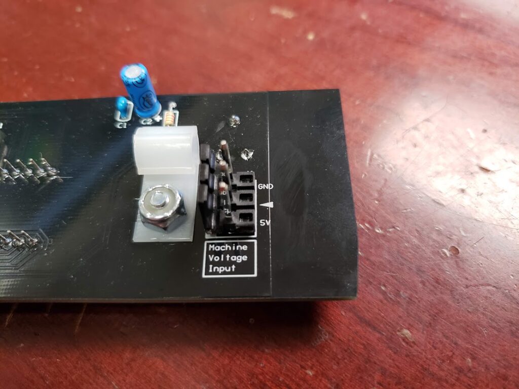
The display assembly has a 3 pin 0.156″ header on the back. This is the main power input for the display. You will need to look at the silkscreen on this header and make a connector that supplies a solid ground and a solid +5vdc. Just make sure it is plugged in the correct orientation.

Arduino Nano

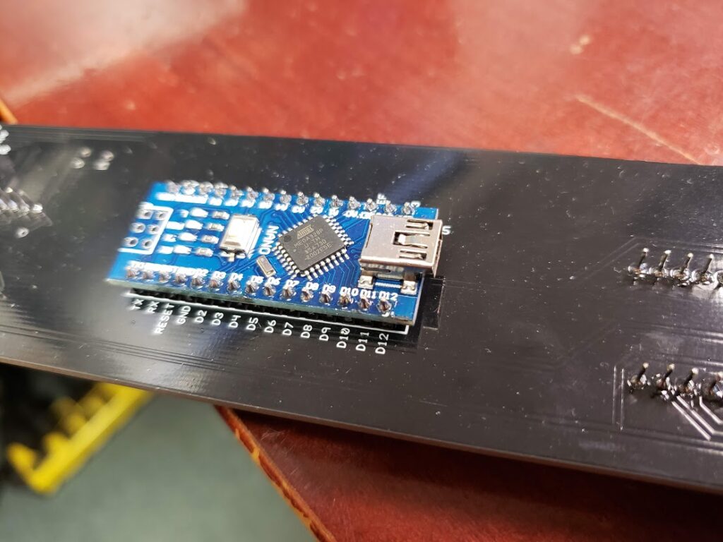
On the back of the display assembly, you will find a pre-programmed Arduino Nano ready for you to send it some instructions. This Arduino will not power up with the main power input and will need to be plugged into an active USB port to come alive. This is a Mini USB connection. Make sure when plugging this in, you use the included strain relief located by the main power input header.

Sending Data

Now into the more fun stuff. The display assembly needs to be sent some serial data from the USB to the Arduino in order to display stuff. I am going to provide some Python samples, but honestly all that is happening here is the PC is just sending the display a line of text. The Arduino will parse it, do all the heavy lifting, and display the numbers on the LED displays!

Text Format

The Arduino is looking for a text string in the following format.

"A:B:C\n"

A: A is the mode of the display. This can indicate whether you want the score to flash, not flash, clear the data, or flash a match (last 2 char flashing).
1 = Not Flashing, just display the score
2 = Flashing, used for current player up
3 = Clear the display
4 = Match display, will flash the last 2 characters of the score

B: B is the number of the display. This value will be between 1 and 4. This is so you can address the correct display when sending score data.

C: C is the actual score! This is a numeric value between 0 and 99999999. Do not put commas here, the Arduino will handle that.

\n: This is the terminating character so the Arduino knows it got a complete line of code.

Examples

Example 1:

"2:1:100000\n"

In this example, the first display will receive a flashing on 100,000.

Example 2:

"1:2:200000\n"

This example will display 200,000 solidly on display number 2.

Example 3:

"3:1:0\n"

This example will completely clear display number 1.

Python Code Examples

In order to send serial text strings over USB with python, I use PySerial. This will allow we to easily send this data to the display assembly.

Opening The Serial Port

    def openSerial(self):
        i = 0
        while (self.serialOpen == False and i <= 9):
            try:
                device_path = '/dev/ttyUSB' + str(i)
                self.game.log('Attempting to open serial port ' + device_path)
                self.ser = serial.Serial(device_path, 115200)  # attempt to open serial port
                self.serialOpen = self.ser.is_open
                self.game.log('Serial Info:')
                self.game.log(str(self.ser))
                self.serialOpen = True
            except:
                self.game.log('Attempt failed to open serial port ' + device_path)
                i = i + 1

This code will scan through the USB devices and try to connect to the Arduino. This code is probably not the best way to do it, but it has worked out well for the TNA project. 🙂

Closing The Serial Connection

    def closeSerial(self):
        try:
            self.ser.close()
            self.serialOpen = False
        except:
            self.game.log('Attempt failed to close serial port')
            self.serialOpen = False

Testing and Sending Data To The Display

    def testSerial(self,String="1234567"):
        self.ser.write("1:1:" + String + "\n")
        self.ser.write("1:2:" + String + "\n")
        self.ser.write("1:3:" + String + "\n")
        self.ser.write("1:4:" + String + "\n")

The above code will be how you should be able to send the data to the display assembly! This test method will send the score of 1,234,567 to all 4 displays.

I wanted to take a moment to thank Jim Askey (MyPinballs). This text string is based off of a serial data project that he did for integrating Bally displays into P-ROC games back in the day. I really liked the text format, so I kept within the same style for this, but added extra functions. Thank you Jim!

That should be all you need to get running. If you find any errors in any of this, please let me know here and I will correct it.

Thanks Everyone!

Hi Everyone,

When developing a pinball machine early on, there will be a need to actually flip the game and check geometry. Since the game is very early in the build and most people do not have a dedicated rig with a computer/driver system in it to test with and will need to wire up some flippers. Since I have gotten many questions about powering up flippers on their homebrew pinball machines, I figured I would take some time to walk through my opinion on the best way to do it.

Hard Wired System 11 Flipper System

This is my preferred way of testing out early geometry as it will emulate production flipper behavior 100%. The below instructions are assuming just 2 flippers for simplicity, but this can be applied to as many flippers as your game has. I am also assuming that the playfield is in a cabinet with flipper buttons installed. 🙂 These flipper assemblies are also very robust and reliable to use in the production or final version of your homebrew game.

Items needed:

Hookup Method

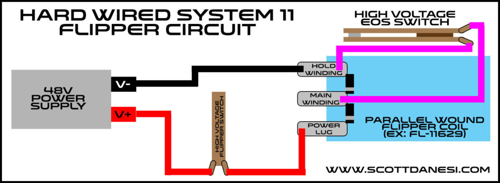
After your flipper assemblies and flipper switches are installed on your playfield and cabinet, you can begin the process of temporarily wiring these up. The wire routing starts at the positive (V+) side of your power supply. You then need to run a wire from this V+ connection to one side of your high voltage flipper switches. The side does not matter as a switch does not care. You will then run this line from your flipper switch to the power lug on your parallel wound coil. You then need to run a line from your negative (V-) side of your power supply to the hold winding lug of your coil. This is the lug that is on the opposite side of the power lug.

You should now be able to check that your normally closed EOS switch is being opened on a full stroke of the flipper. Once this is adjusted, power it up and flip away.

For those of you that are more visual learners like myself, I drew up a crude wiring diagram for you below.

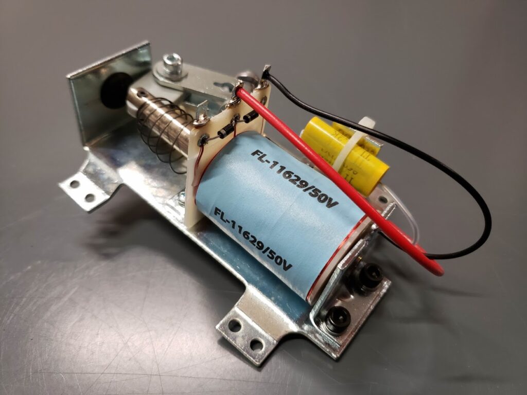
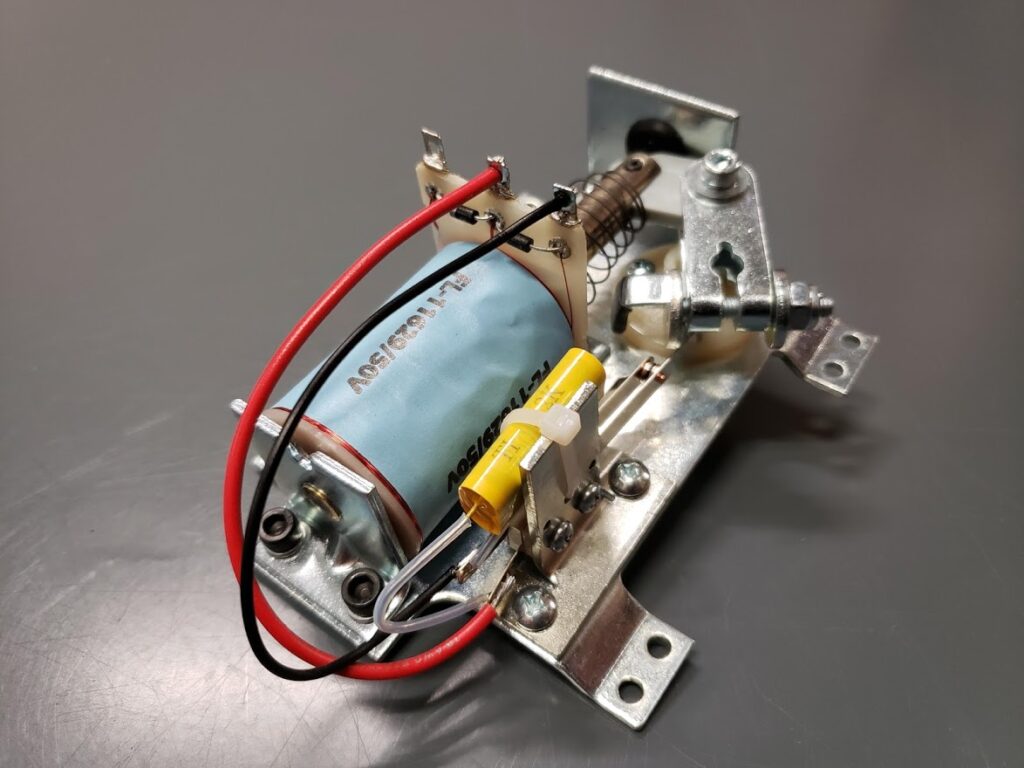
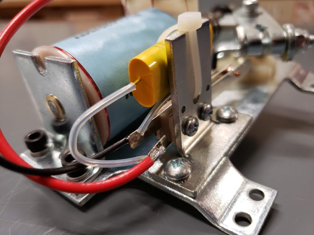
Here are a few close up pics of the System 11 Flipper Assembly

Some notes

  • You can choose to put the high voltage flipper switch on the negative line if you want, it does not matter in this case. I choose to switch the positive, so there is less risk of shorting it to ground when tinkering under the playfield.
  • In this configuration, your flippers will be active whenever the power supply is on.
  • The System 11 Flipper Assemblies may have yellow spark arresting capacitors on the EOS switch. Leave those on there as this will help prolong the life of your EOS switch. 🙂
  • These System 11 Flipper Assemblies, in my opinion, are far superior to the WPC ones since the compression spring is less likely to break causing the game to be down. Almost everything else is the same.
  • DO NOT USE THIS METHOD WITH A TRANSFORMER. Use a switcher power supply only.

Now, this is only a temporary solution as the flippers will be active as soon as you power on the machine every time. When you decide to hook up your control system, you will need to remove the EOS switch, route the 2 winding lugs to 2 channels of your driver board, then route the power lug to the fused output of your driver circuit. The flipper switch will need to be swapped out for a low voltage variety and connected to your switch board. You can now configure your control system to use this flipper assembly!

That is basically it, if you notice any errors in this quick article, embarrassing spelling errors or have any questions about this, please hit me up here.

Disclaimer: If you blow up stuff, or burn down your game/house, I do not take any responsibility. Just double check everything before you power it up. If something is majorly wrong, a switching power supply will shut everything down before anything catches fire usually, so don’t stress, but double check!!!

Thank you and good luck everyone!

Hi Everyone! I just wanted to post this up for all that missed my instructional live jam on my modular rig this morning. I had a great time, and it was fun talking with a bunch of you that I have not seen in a while.

If you have not followed me on Twitch and are interested to see other times when I go live, please follow me at twitch.tv/scottdanesi. I also use my Twitch channel to host some really great music producers, so be sure to check them out as well!

Thank you and enjoy!

Hey Everyone,

I get asked this questions a bunch and figured I would do a quick write-up on what is needed to add light-up flipper buttons to TNA.  

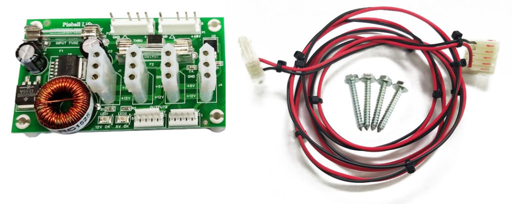
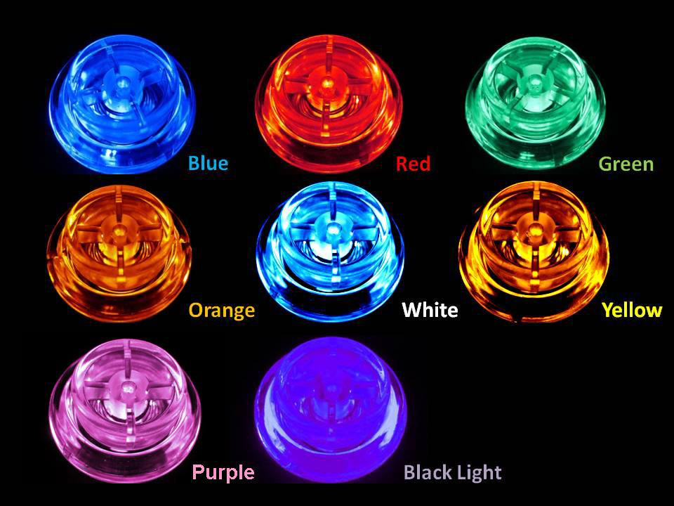
This is actually pretty easy.  You will need 2 things.  The Accessory Power Supply for Spooky P-ROC games and a set of BriteButtons for Stern SAM/Whitestar games.  These 2 items are below:

Each of these items comes with instructions on how to install them.  Obviously, install the Accessory Power Supply first and then the Britebuttons.  The buttons will plug directly into the power supply using the 3 pin Molex connector.  You can then power the machine up and set the mode you want using the details from the instructions in the BriteButtons.

Done!  Have fun!

Hey Everyone, it has been a long time since I did an actual pinball related blog post, so here it is!  I have been getting a ton of questions lately on how to properly power opto transmitter LEDs and how to hook up the receivers to the SW-16 P-ROC boards.  I am going to walk through it in enough detail that you should be able to get up running on the concepts quickly.

Powering Opto Transmitters

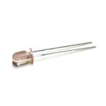
Opto transmitters are nothing more than high powered infrared LEDs.  For this guide, I am going to be referring to the Williams/Bally style opto transmitter which can be seen here: https://www.pinballlife.com/williamsbally-led-transmitter-emitter-for-opto-assemblies.html.  This LED emitter has no circuitry attached to it by default.  These LED emitters are also used on the small PCB and bracket assemblies seen here: https://www.pinballlife.com/williamsbally-led-transmitter-emitter-and-pcb-board.html and other various trough board assemblies.

In order to safely power this LED, you will need to gather a few data points and make a couple small decisions.  You will need to know the forward voltage of the LED, maximum constant current that the LED can handle, decide what input voltage you would like to supply to it (5v or 12v), and decide how much current you would like to give the LED to ensure it has enough power to transmit infrared light to reach your opto receiver.

So here is our data:

  • Forward Voltage: 1.7v
  • Max Constant Current: 100ma, but I recommend you do not exceed 75ma to maximize the life of the LED.  This will be powerful enough to transmit a pretty decent amount of distance between the emitter and receiver.
  • Input Source Voltage: 5vdc is my recommendation as it is higher than the forward voltage of the LED, and low enough that the resistor does not have to dissipate too much heat.

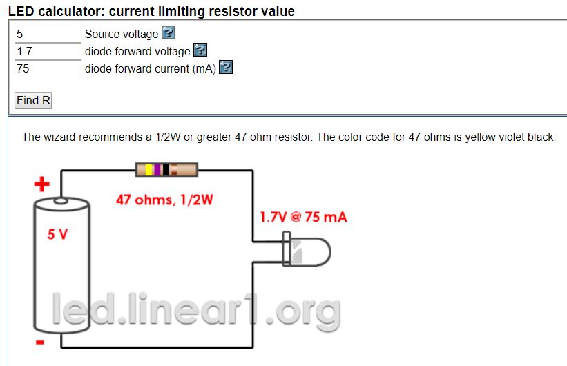
These LED emitters will need a current limiting resistor in series with them as applying 5v or 12v directly to the LED will cause it to overload and fail.  Now, to calculate this resistor value, we will need to calculate resistance and power based on the data that we have.  Now, I could be idealistic and talk about the actual calculations, but I am going to show you how I usually calculate this using an online LED resistor calculator.  The one that I use the most is the one below.  I have already filled out the fields, but feel free to change some of the values up to see what happens.

http://led.linear1.org/1led.wiz?VS=5;VF=1.7;ID=75

So as you can see above, the calculator has automatically figured out what the ohms and recommended resistor wattage should be for our emitter.  What I also like about this calculator is that it gives a nice visual representation of how to wire the circuit and what the resistor color bands are.

Important note: Please be sure to use at least the recommended resistor wattage.  You can see above that the calculator is recommending at least a 1/2 watt resistor.  Too small of a resistor and it can burn up, which is bad.  🙂

That is about it for powering an opto emitter!

Connecting Opto Receivers to the SW-16 P-ROC Board

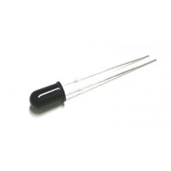
Now for this section, I am going to be talking about the Williams/Bally style opto receivers and how they hook up to the SW-16 P-ROC switch boards.  These are the black colored opto receivers that can be fond here: https://www.pinballlife.com/williamsbally-led-receiver-for-opto-assemblies.html.  These, just like the emitters, are also used in small PCB assemblies, and trough opto boards as well.

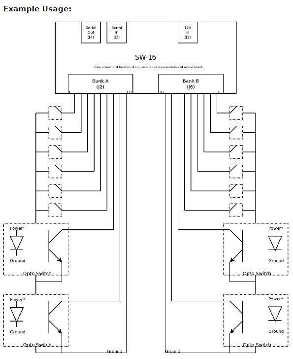
To connect these optos into the SW-16 P-ROC board, you will simply need to wire it directly to the inputs of your switch board.  It is really that easy.  It will act just like a standard switch as long as it is connected in the correct orientation.  Below, you will see an image from the P-ROC documentation.  The cathode/ground side of this diode is the side with the flat indentation on the black epoxy base of the opto.  Please also keep in mind that opto receivers are normally closed switches and when it detects the IR beam from the emitter, it will open.  This is opposite of a normal switch.  When a ball breaks the opto beam it will go from a closed state to an open state.

The full documentation can be found here: https://www.multimorphic.com/content/uploads/2017/07/SW-16-2_LLD_v2-0.pdf

I hope this all makes sense and helps you get your project up and running!  Please also keep in mind that some Stern and certain Williams trough boards have resistors built into them on the emitter side.  The guide above will allow you to connect to boards and directly to emitters that have no circuit logic.

Hey Everyone,

Just wanted to post a quick update.  When I was describing my sound system tuning process to a friend, it occurred to me that this could be a pretty cool little update.   I am going to keep it semi-simple as this can be a wormhole of confusing information.

So here is what is going on.  Whenever you have a very powerful sound system that you hobbled together yourself, it is pretty risky to just tune your subwoofers by ear, especially if the output of your amp is close to the RMS rating of your subwoofers.  You can easily blow up a speaker by sending clipped output signal to them from the amp.

What is a clipped signal?  What does it look like?  For this conversation, we are going to pretend that our sound is a perfect sine wave.  The image below shows our perfect sine wave on the left.  On the right side, you can see that the sine wave is now flattened at the top and bottom.  This is called clipping.

Image credit goes to http://modernmixing.com/

Image credit goes to http://modernmixing.com/

Clipping happens when an audio signal is pushed louder than the amp can handle, so some of the data is cut off from the signal itself.

Now, back to my machine…  What I need to do is make sure that none of the audio signals are clipping on my machine, but still drive the amp and subwoofer as hard as possible.  So here are the high level steps that I took to verify that everything was ok.

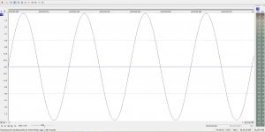
  1. I created a sound sample which was a perfect sine wave running at 50hz (50 cycles per second) and set it to be the default music on the Total Annihilation machine.  (see image below)
    50hz
  2. I then disconnected the audio cable from the computer to the subwoofer amp and hooked up my oscilloscope to the output signal from the computer.  This allowed me to physically view the sound wave on my screen, you know, with my eyes.  This is called checking the pre-amp signal (in case you wanted to know).
  3. I then started a game and took a look at the 50hz sound wave that was now playing.  You can see from the image below that the signal is nice and smooth (no clipping).  Yay!
    sine-wave
  4. Next I plugged the computer audio cable back into the subwoofer amp and disconnected the subwoofer.
  5. The next thing I did was turn down the amp gain all the way to 0% (this is important).
  6. The oscilloscope was then hooked up to the high level output of the subwoofer amplifier, just like how the speaker is hooked up.
  7. I started another game to get the 50hz signal playing.
  8. Then I turned the gain amp up slowly until I could start seeing the sine wave.  I kept going until I saw a bit of clipping in the signal and then backed it down slightly under that limit.  This is simply called the amplifier signal (post amplified signal).
  9. Success!  This now has set my amp to it’s maximum clean output and I will not have to worry about blowing the (not cheap) subwoofer in my game***.   ***Yes, I could technically still blow it, but we do not have to talk about that now…
    20160622_192517

OK, OK, so there are a TON of technical details and nuances that I purposely left out of this post as it would have made it not fun to read.

Well, that is about it.  You now know how to properly check your audio amps for clipping.  All you need is some time and an oscilloscope.  🙂  Also, the sound system has never sounded so good in Total Annihilation.

See you guys/gals at Expo 2016!

Hey Everyone,

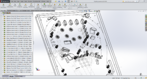
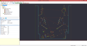
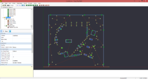
After populating my V1 playfield and testing a few things out, I discovered that my upper right kickback design was not very smooth and I just could not live with the design as it seemed amateur to me.  I ended up replacing the upper right side of the design with some straight inline drops with a scoop behind them.  I am going to do some really cool ball locking tricks with this setup and it will be much better than the original design.  Below is a rendering of the upper section of the V2 playfield that I updated.

A

So on a separate note, I have gotten a bunch of questions on how the hell I am milling a full sized playfield on an X-Carve that is only capable of doing 31″ x 31″.  The process is not that difficult.  Here are the high level steps that I perform to get my playfields cut.

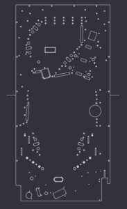
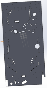
Step 1: Export the full DXF file of my playfield from SolidWorks.  You will notice in the 2 images below there are 2 little lines sticking out of the right and left side of the playfield.  These will be referenced in the next few steps.

 21

Step 2: Import the full DXF into my CAM program and delete all the lines and artifacts ABOVE the 2 guide lines.  I then program the CAM and save as “Playfield Bottom”.

3

Step 3: Import the full DXF again to a new document and delete all the lines and artifacts BELOW the guide lines.  I then program the CAM and save as “Playfield Top”.

4

Step 4: It is important to make sure that the X (left/right) axis is the same for both the top and bottom playfield.  I ensure this happens by setting my X axis to the tip of the left guide line.  This will ensure that the left and right positioning of the 2 cuts are parallel.

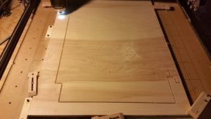
Step 5: Start cutting the bottom part of the playfield and return the machine to X0 Y0 when complete.

5

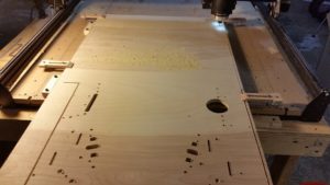
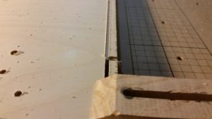
Step 6: Once the bottom part of the playfield is cut, I unlock and slide the stock down and align the tip of the left guide line to the center of the end mill bit.  Once I am happy with the Y alignment, I lock the stock back in place.  I then proceed to cut the top part of the playfield without resetting my X or Y axis in the software.  The machine will pick up where it left off and hopefully continue like it was all cut at once.  It is not perfect every single time, but it is damn close.

6 7

Step 7: Let the machine continue and do not set your beer by the Emergency Stop button.

Hey Everyone,

So I have been getting a few questions about how to properly connect an LED sign to my tournament software.  It is actually pretty simple and I will walk you through it below.

Supported Displays:

First things first, let’s talk about supported displays.  Currently, I have only tested the software with my BetaBrite 213C and my Alpha 220C.  These are some of the most common signs you can find that are affordable.  The BetaBrite signs also came included in the Tournament TOPS Kits from Stern Pinball.  I plan on testing other types and brands very soon.

Display Connection:

BetaBrite Connection Info2

This diagram illustrates the display connection to your PC

These signs use a serial (aka. RS-232 or DB9) connection to your PC.  This type of connection is now very uncommon and is most likely not included on that nice new laptop you bought.  Don’t worry though, many products still use this protocol and there are USB to Serial Adapters available for cheap.  I would recommend getting a USB to Serial adapter with the FTDI Chipset as I have not tested any other type.  If you are lucky enough to have a serial connection on your PC then this is not a problem.  I still like to use the USB to Serial adapter since it will also extend the range of the cable that came with your display.

Cable 1

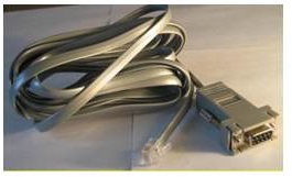
BetaBrite Serial Display Cable

Speaking of which, you should have received a cable with your display that has a serial connection on one end and a network type plug on the other.  If you do not have this cable, don’t worry as they are inexpensive and can be found on eBay.

Once you have all the necessary cables you will need to hook them together and power up the display.

Configuration:

Configuring the sign to work with the software is probably the easiest part.  The one thing you will need to know is what “COM Port” number that your serial connection is set to.  This is a whole number that is usually under 10.  You can find this number by going to your control panel in windows and selecting Device Manager.  Your serial port will be listed under the “Ports” section and have the COM Port displayed in the title.

Once you have this port number, you can now open up the Tournament Manager application.  At this point be sure that your display is connected properly and powered on.  Click on the options tab and then click on the BetaBrite Options tab.  First select the COM port for your serial connection and then check the “Primary Display Output Enabled” checkbox.

Your display should show the test message!  From here you can setup a “Standby” message that will display on the BetaBrite while you are setting up the tournament.  You can use it to say when the tournament is starting and how much it costs to enter or whatever you want.  🙂

References:

BetaBrite Cables on eBay

USB to Serial Cables on Amazon

As always, let me know if you have any questions.

–Scott