Hardware

Finally upgraded all my main patch cables to something I am super happy with. These are @ctrlmod BT patch cables. They are thin, bend nicely, and have a low profile barrel. By far the ones I am most happy with. I ended up color coding by length in rainbow order, so I can quickly grab a longer or shorter cable without thinking. Also, it looks neat when they are hanging. 🙂 Just thought I would share as I know finding patch cables you are happy with is tough.

Hey Pinball Homebrewers!

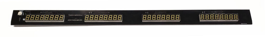
I have had a couple people ask me about using the Total Nuclear Annihilation Numeric Score Displays in their homebrew games. Now that Pinball Life has these display assemblies in stock, I figured I would do a little tutorial on how to use these.

https://www.pinballlife.com/mm5/merchant.mvc?Screen=PROD&Product_Code=PBL-600-0473-00

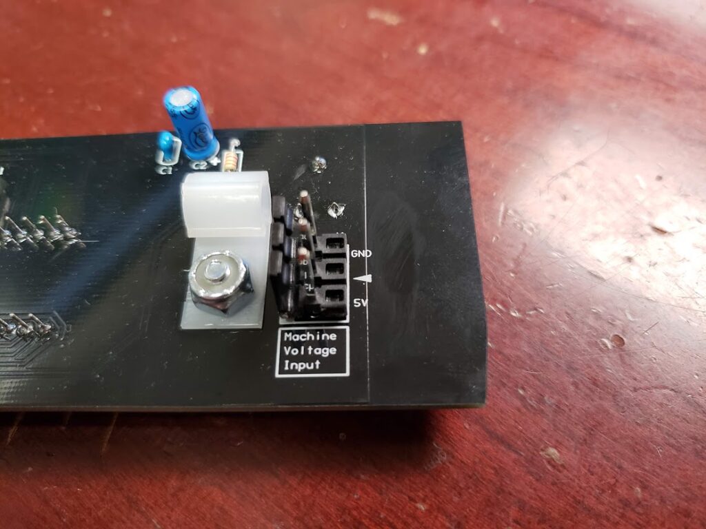
Powering up the display

The display assembly has a 3 pin 0.156″ header on the back. This is the main power input for the display. You will need to look at the silkscreen on this header and make a connector that supplies a solid ground and a solid +5vdc. Just make sure it is plugged in the correct orientation.
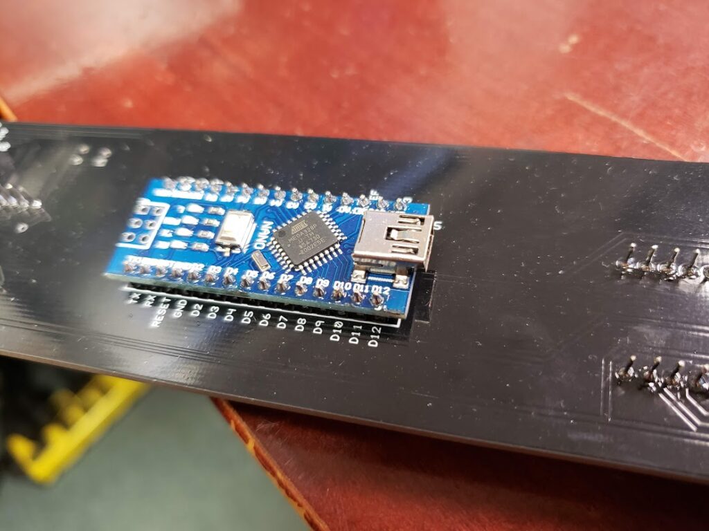
Arduino Nano

On the back of the display assembly, you will find a pre-programmed Arduino Nano ready for you to send it some instructions. This Arduino will not power up with the main power input and will need to be plugged into an active USB port to come alive. This is a Mini USB connection. Make sure when plugging this in, you use the included strain relief located by the main power input header.

Sending Data

Now into the more fun stuff. The display assembly needs to be sent some serial data from the USB to the Arduino in order to display stuff. I am going to provide some Python samples, but honestly all that is happening here is the PC is just sending the display a line of text. The Arduino will parse it, do all the heavy lifting, and display the numbers on the LED displays!

Text Format

The Arduino is looking for a text string in the following format.

"A:B:C\n"

A: A is the mode of the display. This can indicate whether you want the score to flash, not flash, clear the data, or flash a match (last 2 char flashing).
1 = Not Flashing, just display the score
2 = Flashing, used for current player up
3 = Clear the display
4 = Match display, will flash the last 2 characters of the score

B: B is the number of the display. This value will be between 1 and 4. This is so you can address the correct display when sending score data.

C: C is the actual score! This is a numeric value between 0 and 99999999. Do not put commas here, the Arduino will handle that.

\n: This is the terminating character so the Arduino knows it got a complete line of code.

Examples

Example 1:

"2:1:100000\n"

In this example, the first display will receive a flashing on 100,000.

Example 2:

"1:2:200000\n"

This example will display 200,000 solidly on display number 2.

Example 3:

"3:1:0\n"

This example will completely clear display number 1.

Python Code Examples

In order to send serial text strings over USB with python, I use PySerial. This will allow we to easily send this data to the display assembly.

Opening The Serial Port

    def openSerial(self):
        i = 0
        while (self.serialOpen == False and i <= 9):
            try:
                device_path = '/dev/ttyUSB' + str(i)
                self.game.log('Attempting to open serial port ' + device_path)
                self.ser = serial.Serial(device_path, 115200)  # attempt to open serial port
                self.serialOpen = self.ser.is_open
                self.game.log('Serial Info:')
                self.game.log(str(self.ser))
                self.serialOpen = True
            except:
                self.game.log('Attempt failed to open serial port ' + device_path)
                i = i + 1

This code will scan through the USB devices and try to connect to the Arduino. This code is probably not the best way to do it, but it has worked out well for the TNA project. 🙂

Closing The Serial Connection

    def closeSerial(self):
        try:
            self.ser.close()
            self.serialOpen = False
        except:
            self.game.log('Attempt failed to close serial port')
            self.serialOpen = False

Testing and Sending Data To The Display

    def testSerial(self,String="1234567"):
        self.ser.write("1:1:" + String + "\n")
        self.ser.write("1:2:" + String + "\n")
        self.ser.write("1:3:" + String + "\n")
        self.ser.write("1:4:" + String + "\n")

The above code will be how you should be able to send the data to the display assembly! This test method will send the score of 1,234,567 to all 4 displays.

I wanted to take a moment to thank Jim Askey (MyPinballs). This text string is based off of a serial data project that he did for integrating Bally displays into P-ROC games back in the day. I really liked the text format, so I kept within the same style for this, but added extra functions. Thank you Jim!

That should be all you need to get running. If you find any errors in any of this, please let me know here and I will correct it.

Thanks Everyone!

Hi Everyone,

When developing a pinball machine early on, there will be a need to actually flip the game and check geometry. Since the game is very early in the build and most people do not have a dedicated rig with a computer/driver system in it to test with and will need to wire up some flippers. Since I have gotten many questions about powering up flippers on their homebrew pinball machines, I figured I would take some time to walk through my opinion on the best way to do it.

Hard Wired System 11 Flipper System

This is my preferred way of testing out early geometry as it will emulate production flipper behavior 100%. The below instructions are assuming just 2 flippers for simplicity, but this can be applied to as many flippers as your game has. I am also assuming that the playfield is in a cabinet with flipper buttons installed. 🙂 These flipper assemblies are also very robust and reliable to use in the production or final version of your homebrew game.

Items needed:

Hookup Method

After your flipper assemblies and flipper switches are installed on your playfield and cabinet, you can begin the process of temporarily wiring these up. The wire routing starts at the positive (V+) side of your power supply. You then need to run a wire from this V+ connection to one side of your high voltage flipper switches. The side does not matter as a switch does not care. You will then run this line from your flipper switch to the power lug on your parallel wound coil. You then need to run a line from your negative (V-) side of your power supply to the hold winding lug of your coil. This is the lug that is on the opposite side of the power lug.

You should now be able to check that your normally closed EOS switch is being opened on a full stroke of the flipper. Once this is adjusted, power it up and flip away.

For those of you that are more visual learners like myself, I drew up a crude wiring diagram for you below.

Here are a few close up pics of the System 11 Flipper Assembly

Some notes

  • You can choose to put the high voltage flipper switch on the negative line if you want, it does not matter in this case. I choose to switch the positive, so there is less risk of shorting it to ground when tinkering under the playfield.
  • In this configuration, your flippers will be active whenever the power supply is on.
  • The System 11 Flipper Assemblies may have yellow spark arresting capacitors on the EOS switch. Leave those on there as this will help prolong the life of your EOS switch. 🙂
  • These System 11 Flipper Assemblies, in my opinion, are far superior to the WPC ones since the compression spring is less likely to break causing the game to be down. Almost everything else is the same.
  • DO NOT USE THIS METHOD WITH A TRANSFORMER. Use a switcher power supply only.

Now, this is only a temporary solution as the flippers will be active as soon as you power on the machine every time. When you decide to hook up your control system, you will need to remove the EOS switch, route the 2 winding lugs to 2 channels of your driver board, then route the power lug to the fused output of your driver circuit. The flipper switch will need to be swapped out for a low voltage variety and connected to your switch board. You can now configure your control system to use this flipper assembly!

That is basically it, if you notice any errors in this quick article, embarrassing spelling errors or have any questions about this, please hit me up here.

Disclaimer: If you blow up stuff, or burn down your game/house, I do not take any responsibility. Just double check everything before you power it up. If something is majorly wrong, a switching power supply will shut everything down before anything catches fire usually, so don’t stress, but double check!!!

Thank you and good luck everyone!

Hi Everyone! I just wanted to post this up for all that missed my instructional live jam on my modular rig this morning. I had a great time, and it was fun talking with a bunch of you that I have not seen in a while.

If you have not followed me on Twitch and are interested to see other times when I go live, please follow me at twitch.tv/scottdanesi. I also use my Twitch channel to host some really great music producers, so be sure to check them out as well!

Thank you and enjoy!

Hey Everyone, it has been a long time since I did an actual pinball related blog post, so here it is!  I have been getting a ton of questions lately on how to properly power opto transmitter LEDs and how to hook up the receivers to the SW-16 P-ROC boards.  I am going to walk through it in enough detail that you should be able to get up running on the concepts quickly.

Powering Opto Transmitters

Opto transmitters are nothing more than high powered infrared LEDs.  For this guide, I am going to be referring to the Williams/Bally style opto transmitter which can be seen here: https://www.pinballlife.com/williamsbally-led-transmitter-emitter-for-opto-assemblies.html.  This LED emitter has no circuitry attached to it by default.  These LED emitters are also used on the small PCB and bracket assemblies seen here: https://www.pinballlife.com/williamsbally-led-transmitter-emitter-and-pcb-board.html and other various trough board assemblies.

In order to safely power this LED, you will need to gather a few data points and make a couple small decisions.  You will need to know the forward voltage of the LED, maximum constant current that the LED can handle, decide what input voltage you would like to supply to it (5v or 12v), and decide how much current you would like to give the LED to ensure it has enough power to transmit infrared light to reach your opto receiver.

So here is our data:

  • Forward Voltage: 1.7v
  • Max Constant Current: 100ma, but I recommend you do not exceed 75ma to maximize the life of the LED.  This will be powerful enough to transmit a pretty decent amount of distance between the emitter and receiver.
  • Input Source Voltage: 5vdc is my recommendation as it is higher than the forward voltage of the LED, and low enough that the resistor does not have to dissipate too much heat.

These LED emitters will need a current limiting resistor in series with them as applying 5v or 12v directly to the LED will cause it to overload and fail.  Now, to calculate this resistor value, we will need to calculate resistance and power based on the data that we have.  Now, I could be idealistic and talk about the actual calculations, but I am going to show you how I usually calculate this using an online LED resistor calculator.  The one that I use the most is the one below.  I have already filled out the fields, but feel free to change some of the values up to see what happens.

http://led.linear1.org/1led.wiz?VS=5;VF=1.7;ID=75

So as you can see above, the calculator has automatically figured out what the ohms and recommended resistor wattage should be for our emitter.  What I also like about this calculator is that it gives a nice visual representation of how to wire the circuit and what the resistor color bands are.

Important note: Please be sure to use at least the recommended resistor wattage.  You can see above that the calculator is recommending at least a 1/2 watt resistor.  Too small of a resistor and it can burn up, which is bad.  🙂

That is about it for powering an opto emitter!

Connecting Opto Receivers to the SW-16 P-ROC Board

Now for this section, I am going to be talking about the Williams/Bally style opto receivers and how they hook up to the SW-16 P-ROC switch boards.  These are the black colored opto receivers that can be fond here: https://www.pinballlife.com/williamsbally-led-receiver-for-opto-assemblies.html.  These, just like the emitters, are also used in small PCB assemblies, and trough opto boards as well.

To connect these optos into the SW-16 P-ROC board, you will simply need to wire it directly to the inputs of your switch board.  It is really that easy.  It will act just like a standard switch as long as it is connected in the correct orientation.  Below, you will see an image from the P-ROC documentation.  The cathode/ground side of this diode is the side with the flat indentation on the black epoxy base of the opto.  Please also keep in mind that opto receivers are normally closed switches and when it detects the IR beam from the emitter, it will open.  This is opposite of a normal switch.  When a ball breaks the opto beam it will go from a closed state to an open state.

The full documentation can be found here: https://www.multimorphic.com/content/uploads/2017/07/SW-16-2_LLD_v2-0.pdf

I hope this all makes sense and helps you get your project up and running!  Please also keep in mind that some Stern and certain Williams trough boards have resistors built into them on the emitter side.  The guide above will allow you to connect to boards and directly to emitters that have no circuit logic.

Earthshaker Aftershock Logo 1Hey Everyone,

I finally got around to starting my Earthshaker software rewrite project.  I decided to call this project Earthshaker Aftershock.

Overall Goal:
The plan for this project is to redo the entire code for Earthshaker and take advantage of it’s great playfield layout.  As we all know Earthshaker is a great game as it sits, but I feel it could be so much more.  I will be posting updates throughout the project and I hope to have something to show for Expo next year!  Let me know if you guys have any questions or suggestions.  I am always open to feedback (positive or negative).

This code will not be for sale but will be available on my GitHub account for those of you who want to check it out.

https://github.com/scottdanesi/earthshaker-aftershock

Please note that this code is built on the P-ROC and Procgame framework and cannot be run on an Earthshaker machine without extensive customization to the machine hardware itself.

Software:
I will be adding all new mini-modes along with new audio and display interaction.  I will keep the game easy to understand for novice players and deep enough for the most experienced.

Hardware:
I have in my possession Earthshaker prototype #2 (at least most of it) and I will be using that machine for my software re-write.  I do not plan on adding a DMD, I will be using the stock Alphanumeric displays (Thank you Jim).  I have also acquired one of Mark’s System 11 P-ROC interface boards!  This project is going to be great.

Updates:
I will be updating my topic on the Pinballcontrollers.com forum with technical updates.  You can visit the link here: http://www.pinballcontrollers.com/forum/index.php?topic=1001.0

As a first update, here is a video of my proof of concept code which allows me to test all of the hardware interaction with the P-ROC and the computer.

Hey Everyone,

So I have been getting a few questions about how to properly connect an LED sign to my tournament software.  It is actually pretty simple and I will walk you through it below.

Supported Displays:

First things first, let’s talk about supported displays.  Currently, I have only tested the software with my BetaBrite 213C and my Alpha 220C.  These are some of the most common signs you can find that are affordable.  The BetaBrite signs also came included in the Tournament TOPS Kits from Stern Pinball.  I plan on testing other types and brands very soon.

Display Connection:

BetaBrite Connection Info2

This diagram illustrates the display connection to your PC

These signs use a serial (aka. RS-232 or DB9) connection to your PC.  This type of connection is now very uncommon and is most likely not included on that nice new laptop you bought.  Don’t worry though, many products still use this protocol and there are USB to Serial Adapters available for cheap.  I would recommend getting a USB to Serial adapter with the FTDI Chipset as I have not tested any other type.  If you are lucky enough to have a serial connection on your PC then this is not a problem.  I still like to use the USB to Serial adapter since it will also extend the range of the cable that came with your display.

Cable 1

BetaBrite Serial Display Cable

Speaking of which, you should have received a cable with your display that has a serial connection on one end and a network type plug on the other.  If you do not have this cable, don’t worry as they are inexpensive and can be found on eBay.

Once you have all the necessary cables you will need to hook them together and power up the display.

Configuration:

Configuring the sign to work with the software is probably the easiest part.  The one thing you will need to know is what “COM Port” number that your serial connection is set to.  This is a whole number that is usually under 10.  You can find this number by going to your control panel in windows and selecting Device Manager.  Your serial port will be listed under the “Ports” section and have the COM Port displayed in the title.

Once you have this port number, you can now open up the Tournament Manager application.  At this point be sure that your display is connected properly and powered on.  Click on the options tab and then click on the BetaBrite Options tab.  First select the COM port for your serial connection and then check the “Primary Display Output Enabled” checkbox.

Your display should show the test message!  From here you can setup a “Standby” message that will display on the BetaBrite while you are setting up the tournament.  You can use it to say when the tournament is starting and how much it costs to enter or whatever you want.  🙂

References:

BetaBrite Cables on eBay

USB to Serial Cables on Amazon

As always, let me know if you have any questions.

–Scott