
Hi Everyone,
When developing a pinball machine early on, there will be a need to actually flip the game and check geometry. Since the game is very early in the build and most people do not have a dedicated rig with a computer/driver system in it to test with and will need to wire up some flippers. Since I have gotten many questions about powering up flippers on their homebrew pinball machines, I figured I would take some time to walk through my opinion on the best way to do it.
Hard Wired System 11 Flipper System
This is my preferred way of testing out early geometry as it will emulate production flipper behavior 100%. The below instructions are assuming just 2 flippers for simplicity, but this can be applied to as many flippers as your game has. I am also assuming that the playfield is in a cabinet with flipper buttons installed. 🙂 These flipper assemblies are also very robust and reliable to use in the production or final version of your homebrew game.
Items needed:
- 48v Switching Power supply with at least 600 watt capability
- 2x High Voltage Flipper Switches
- 2x System 11 Flipper Assemblies
- 18AWG Wire
Hookup Method
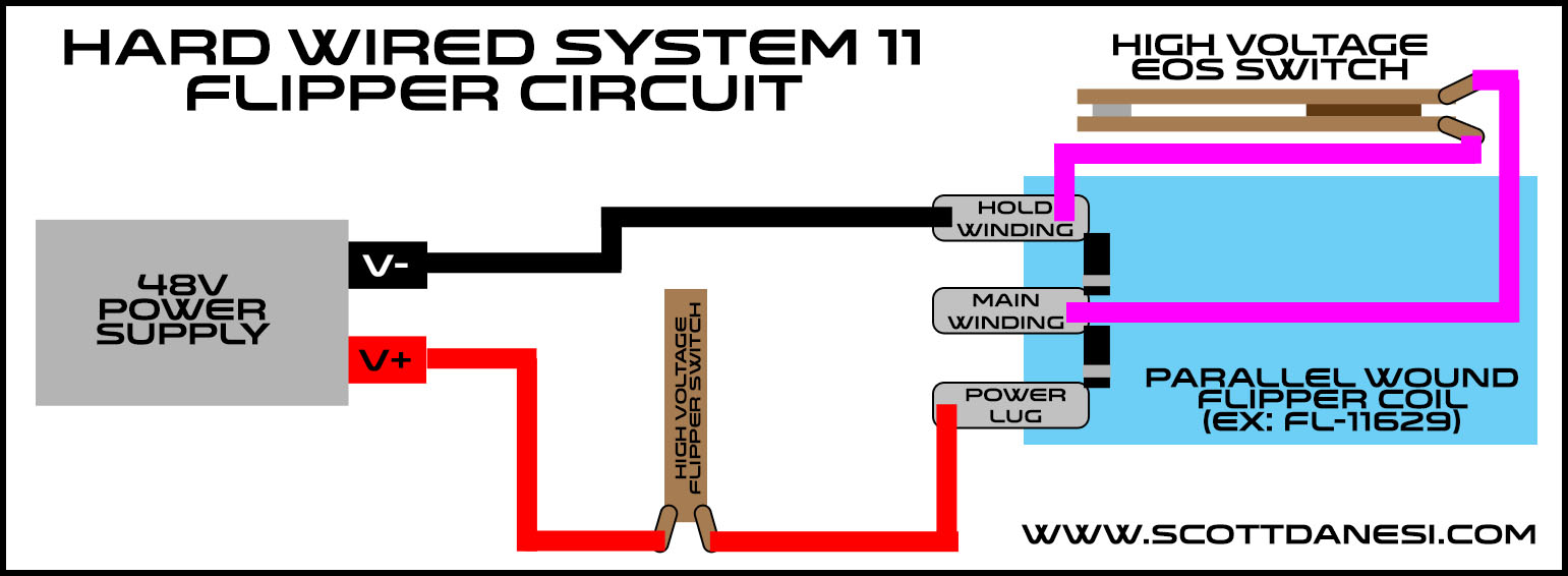
After your flipper assemblies and flipper switches are installed on your playfield and cabinet, you can begin the process of temporarily wiring these up. The wire routing starts at the positive (V+) side of your power supply. You then need to run a wire from this V+ connection to one side of your high voltage flipper switches. The side does not matter as a switch does not care. You will then run this line from your flipper switch to the power lug on your parallel wound coil. You then need to run a line from your negative (V-) side of your power supply to the hold winding lug of your coil. This is the lug that is on the opposite side of the power lug.
You should now be able to check that your normally closed EOS switch is being opened on a full stroke of the flipper. Once this is adjusted, power it up and flip away.
For those of you that are more visual learners like myself, I drew up a crude wiring diagram for you below.
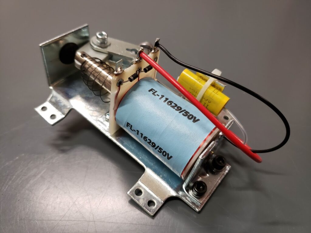
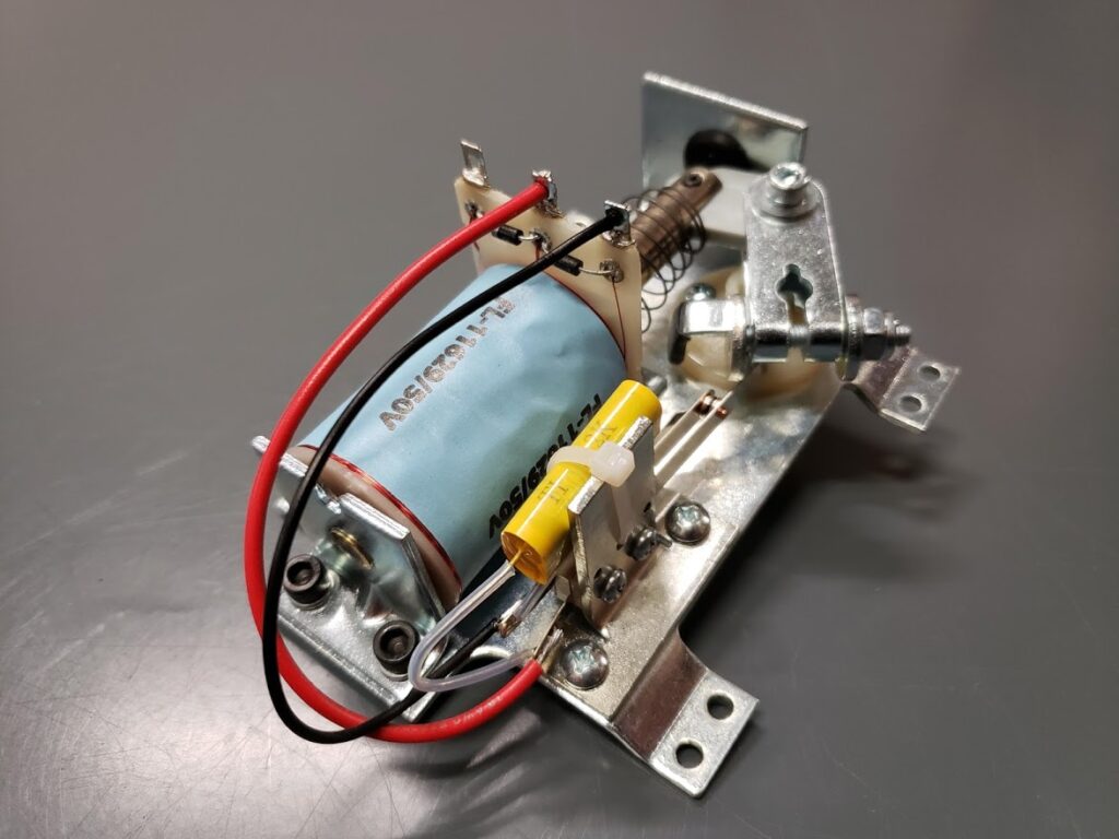
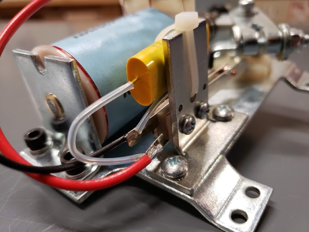
Here are a few close up pics of the System 11 Flipper Assembly
Some notes
- You can choose to put the high voltage flipper switch on the negative line if you want, it does not matter in this case. I choose to switch the positive, so there is less risk of shorting it to ground when tinkering under the playfield.
- In this configuration, your flippers will be active whenever the power supply is on.
- The System 11 Flipper Assemblies may have yellow spark arresting capacitors on the EOS switch. Leave those on there as this will help prolong the life of your EOS switch. 🙂
- These System 11 Flipper Assemblies, in my opinion, are far superior to the WPC ones since the compression spring is less likely to break causing the game to be down. Almost everything else is the same.
- DO NOT USE THIS METHOD WITH A TRANSFORMER. Use a switcher power supply only.
Now, this is only a temporary solution as the flippers will be active as soon as you power on the machine every time. When you decide to hook up your control system, you will need to remove the EOS switch, route the 2 winding lugs to 2 channels of your driver board, then route the power lug to the fused output of your driver circuit. The flipper switch will need to be swapped out for a low voltage variety and connected to your switch board. You can now configure your control system to use this flipper assembly!
That is basically it, if you notice any errors in this quick article, embarrassing spelling errors or have any questions about this, please hit me up here.
Disclaimer: If you blow up stuff, or burn down your game/house, I do not take any responsibility. Just double check everything before you power it up. If something is majorly wrong, a switching power supply will shut everything down before anything catches fire usually, so don’t stress, but double check!!!
Thank you and good luck everyone!

hi , i do not know too much about this ,but I’ve seen other diagrams showing 5 volts for the hold side…so the way this is wired, the EOS shuts off the 48 volts to the high voltage coil? and how does the low voltage coil hold? thanks mike
It really depends on the machine. The coils used in Williams games use high voltage for the hold coil since it has a much higher resistance. It can handle it, no problem. 🙂
Tried this, but the PSU keeps shutting off when I try to hold down the flipper button, think it’s detecting a short. Any ideas?
Hey there! Yes, this can happen if you do not have power capacitors on the main 48v source of your supply. Also, you could potentially have something hooked up incorrectly or have an underpowered supply. I recommend using a 600 watt 48 volt supply for your coils. But first, install a capacitor bank and double check your wiring.
–Scott
Hey, thanks for the reply. What value charging capacitors do you recommend using?
Hey there! I recommend using a bank of 4 or more 6800uf capacitors wire in parallel with the negative and positive rails of your 48v supply. But make sure the voltage is at least 60vdc on the capacitors so they are within the voltage range of your coils.