Arcade Posts

Posts having to do with Arcade Machines and Pinball Machines!

TNA Experience Overview

The Pinball Olympic Stadium in Chicago has the world’s most intense TNA Experience Room. If you do not know what that is, it is a self contained room that Jay Brand (BangerJay) built and I programmed just for the Pinball Olympics.

You can find more information about it here (please let me know if these external links ever break):
https://www.reddit.com/r/pinball/comments/17e9swo/the_total_nuclear_annihilation_full_immersive/
https://www.facebook.com/reel/982567487243878

This room has enough space for 4 players to gather and play TNA in the most extreme pinball environment in existence. This room is completely controlled by the game itself and has over 200 amps of RGB LEDs, 5000watts of audio equipment, and other features like a fog machine and air evacuation system.

As many of you have been asking, I figured I would post this information out here for people to reference on how this was actually built and what was used to interface with the pinball machine. I do not recommend anyone attempt this as it is dangerous and you can easily start you house on fire if something is not hooked up correctly of safely. This overview below is going to be pretty high level and technical. This is also most likely missing information that I can update and add later.

TNA Experience LEDs:

There are speaker light RGB outputs on the game, currently connected to your speaker LEDs.  This is split and attached to a bunch of RGB light strip amplifiers.  Each amplifier can support safely 20 amps at 12vdc (they claim anyway).  Each standard LED light strip reel is about 3 meters, which is about 4 amps (maybe less).  I would probably keep it to about 4 light strips per amplifier just to be safe.  These light strips should NOT be wired in series as they will burn up.  Just wire them in parallel out of the amps.  You will also need a few massive 12vdc power supplies for the light strips.  We are running 3 100amp 12v supplies for the TNA room we just built, but we are planning on adding more.  These power supplies can handle about 4 amplifiers each (again, to be safe).  I did not push these to their limit as I did not want to start the thing on fire.  🙂 Each of the amplifier input signals needs to be put in parallel as well with the signal coming from the game or it will cause issues.  You will also need to hook up the amplifiers to the DC power supply in parallel as well so you are not daisy chaining them together.  If you put them in series, you will burn up wires and could potentially cause a fire.  When assembling this you should current test everything at full power just to be sure nothing gets hot.  Using these guidelines, you can basically add as many LED strips, amps, and power supplies as you want.

TNA Experience Fog:

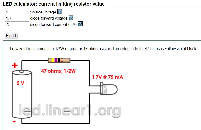
In order to trigger the fog machine, you will need to buy a couple 12v relays that have 12v capable contactors.  These usually can handle 8 amps max.  These relay coils are wired into the beacon light and will click the relay on whenever the beacon is on.  What I did for the fog machine is I took it apart and soldered some wires onto the manual trigger switch and wired those to the normally open side of the relay.  That way the fog machine would trigger when the beacon activated.  The second relay was used to control the high power exhaust fans (air evacuation system).  This relay coil is still connected to the beacon the same way as the first, but then I wired up a 120v outlet to the normally closed side of the relay.  This means that the outlet is giving line level voltage to the fans when the beacon is not on, but when it is on, it will shut the fans off.

TNA Experience Audio:

I simply disconnected the 3.5mm headphone jack from the back of the LCD panel, ran that though a noise filter and external equalizer.  Then into the PA system.  This disables the speakers in the game and uses just the PA, which is good.  I put an EQ on there because at very high volumes the upper level frequencies were in dangerous ear damage range and I just knocked those down.  

Links:

LED Strip Amplifiers: https://www.amazon.com/BTF-LIGHTING-Strip-Amplifier-Controller-5050SMD/dp/B07T6XVYBN/

LED Strip: https://www.amazon.com/SUPERNIGHT-16-4ft-Waterproof-Changing-Lights/dp/B076VG955L/

100amp 12v Power Supplies: https://www.amazon.com/Version-Adapter-Converter-Transformer-Security/dp/B0BXTBBS9M/

12v Relay: https://www.amazon.com/Electronics-Salon-SPST-NO-Module-Control-Voltage/dp/B01B60BQFA/

TNA Experience Miscellaneous and Safety

You will also need a bunch of wire.  I recommend 16awg wire for the power supply to the amplifiers and 18-20awg for the amps to the led strip.  Make sure you use 14awg or larger for the main line input on the power supplies to the wall.  Using 3 power supplies for the LEDs, you are looking at 3600 maximum watts from the circuit.  That is 30 amps, but it will probably use less than 20 amps.  You will want that on a 20 amp dedicated circuit though for the LEDs.  The fog machine, game, and audio system should be on a separate circuit.

I know this is brief and to the point, but I wanted to just get this out there for anyone curious on what we did.

Again, don’t do this. 🙂

Congratulations to VPinWorkshop on the release of the virtual Total Nuclear Annihilation pinball machine! This game is a complete reproduction of TNA that can be played in VR, desktop, and virtual pinball machines. I provided VPinWorkshop the assets and they recreated authentic gameplay. Head over to link below to download. They put so much work into this game and I am excited for everyone to experience it!

https://vpuniverse.com/files/file/14359-total-nuclear-annihilation-spooky-2017-vpw/

This is an interesting question that I get asked from time to time and I realized I have a much longer answer than just “for FOMO”. So here is a nice blog entry about it. 🙂

If you are unaware, many different types of companies that develop products with officially licensed themes keep said licenses a secret during the development cycle for a number of reasons. This is obviously not limited to Pinball and Video Game companies. I am going to list the main reasons that I know about and have been exposed to below, but there are probably many others as well.

Theme, Licensor, and Competitive Edge

The licensee and licensor usually want to keep product development under wraps to get ahead of competing licenses. This also keeps any ideas/designs secret from other companies until the full reveal. Also, there are unfortunate things that could happen behind the scenes if a competing company found out about a theme. Sabotage can happen and licenses can be swept out from under you if you are not careful. For unlicensed themes, this can hurt the company because others could potentially replicate the theme or design elements.

FOMO / Hype and Stagnation

Yes, it is true, a company will want to manage hype around a product, and this is actually important to help drive sales and keep a professional appearance. If a company announced a theme that excites the community at the beginning of the development cycle of said game, this will generate a bunch of hype only have it die down and people lose interest and move on to something else. Development cycles can be pretty long for Pinball Machines and Video Games. It is way more advantageous to keep this under wraps until the product is just about to be released or fully revealed to the world. This also could expose the company to criticism from the outside due to the long time from announcement to product release. This could, and most likely will, hurt the companies reputation.

Avoiding Leaks

Leaks can be damaging to these companies. If a license is revealed too early, it can result in spoilers, reduced sales, and a loss of excitement for the game. Keeping licenses secret helps to prevent these types of leaks, but it is not fool proof as we all know. These leaks could also hurt the original IP as well as it could be for something like an unreleased movie or any other unreleased content. This could really get a company in hot water and could potentially get the license pulled.

The Community “What-Ifs”

This is an interesting one… If a company announced a theme early before or during development, the game community could start throwing ideas out left and right. These ideas cannot all make it into a machine otherwise it will look like a Homer Simpson car and loose all connection to the designer’s vision of what it should be. This complicates things in other ways too. “Hey, I came up with that mech! Where are my royalties, my feelings are hurt, fuck you X company”

Again, there are probably more reasons that I did not cover here, but these are just the ones that pop out to me as the most important. But as you can see, there is more to keeping these themes secret than just trying to control FOMO and hype. Have a great day everyone!

I get this question pretty frequently, so I figured I would post a how to guide on getting the most out of the audio system on your Total Nuclear Annihilation pinball machine.

Do this at your own risk as this has the potential to damage your amp and/or speakers if set too high. But please do not do this unless your amp settings get totally out of whack.

Warning, this setup procedure is going to be loud, so warn the people around you.

Subwoofer Physical Adjustment (do this first):

You may notice some strange distortion coming from the subwoofer… These subwoofers are interference type speakers which means that upon loud use, the speaker cone extends beyond the mounting bracket plane. This will cause the cone to come in contact with the speaker grill and potentially the edge of the bottom of the cabinet. You can get a 10 inch speaker spacer online from various places that will make sure the speaker has enough space to move freely.

Sub Chamber Sealing:

A pinball machine makes a TERRIBLE subwoofer cabinet for a number of reasons, but here are a few. The main reason being that every subwoofer has a recommended cabinet volume specification. These pinball cabinets are MUCH MUCH larger than what the subwoofers call for. The next reason is that pinball cabinets are full of crap that can rattle around upon vibration from the subwoofer making terrible sounds. Another big reason is that pinball cabinets are basically the most leaky thing ever. Porting subwoofer cabinets is important, but having the sound leak out from ever little hole and crack is awful.

OK, so what do we do about this…. In TNA I created a Sub Chamber in the cabinet. This is basically a box that goes around the subwoofer that is pretty close to what the subwoofer wants for volume. This box idealistically will push all of the bass out the bottom of the cabinet. This is great, but unfortunately, it is not perfect in production. The production sub chambers leak a bit as they were not sealed with silicone sealant.

Easy fix though. While you are in there putting a spacer under your subwoofer, it is a great time to pick up some silicone sealant and seal up the inside of the box. I recommend pulling all the screws out from the bottom of the cabinet and removing the Sub Chamber completely. You can then squish this silicone sealant into every join on the inside of the chamber. Once you go to reassemble it, put a bead of silicone on the bottom side where the chamber attaches to the bottom of the cabinet. This will ensure a great seal and improve the sound of the subwoofer.

Adjusting the Amplifier:

Step 1: With the game on, take the backglass out and press the volume up or down button on the back of the LCD and bring the pre-amp volume down to 11. It will show on the screen. This is probably set high from the factory, but I found reducing this made the audio quality slightly better.
Step 2: Put the backglass back in.
Step 3: Turn every knob on your amp all the way down until it stops.
Step 4: Go to Music Test in the service menu and select reactor 3 by pressing the start button a few times.
Step 5: On the coin door, press the volume up button until it reaches 11.
Step 6: On the amp, turn the second knob from the left (sub crossover) up about 1/8 turn.
Step 7: On the amp, turn the treble just past half way up.
Step 8: On the amp turn the Bass knob up about 1/8 turn. Keep this low as this is controlling the bass output to the upper speakers and could damage them or the amp if set too high.

Here is where it is going to get loud…

Step 9: On the amp, turn up the sub volume very slowly until just before you hear a bit of distortion. This will be pretty loud.
Step 10: On the amp, turn up the Volume knob slowly until before you hear distortion or you feel that is the loudest you would ever have the machine. This is also the time where adjusting the treble up or down should be done.

Important note! If the amp cuts out during any of these last 2 steps, you went too high with the volume and/or Bass knob. Bring these back down so the amp does not cut out as this could damage it.

Step 11: On the coin door, turn down the volume back to a reasonable level and enjoy.

Again, please do this at your own risk. You can damage your amp and/or speakers messing with this stuff. I am not an expert audiophile or whatever it is called, I am just knowledgeable enough to be dangerous here. Don’t blame me or Spooky if you break something. 

Using an external subwoofer:

If you just cannot get your subwoofer sounding awesome, the easiest thing to do is install an external sub. These are pretty affordable and I recommend using the Polk Audio PSW10. All you do is disconnect the amp output wires on the internal subwoofer and run a new set of wires down to the PSW10s Speaker Level Inputs. You can then do that amp adjustment procedure again without the internal sub hooked up.

Conclusion:

I hope this helps you getting your TNA to sound awesome. If you have any questions or find any errors or better ways of doing this, please contact me and let me know. Enjoy!

Final note: I put a few Amazon links in this blog post that are linked to the Danesi Designs Affiliate Program. I did this to hopefully help generate a little bit of passive income. Thank you everyone very much!

It is here! v1.5.0 has finally arrived. This new version contains some exciting new stuff including a brand new Jukebox Mode, even more Scorbit integrations, and a Spinner Rip counter with dedicated high score table. This version and all future versions are fully compatible with all versions of the Total Nuclear Annihilation pinball machine.

Below is the full changlog for this release.

####################################################################################
v1.5.0 - 10/05/2022 - Scott Danesi

## Bugs Fixed ##
- Fixed issue with music resetting at the end of multiball when it was not necessary to restart the song
- Slight sound effect mix balancing
- Scorbit misc bug fixes
- Fixed bug where the game would not allow you to completely erase your name on the high score name entry screen

## Features Added / Modifications ##
- Added support for the upgraded core numeric display
- Lightshows updated to include new RGB LEDs in upgraded core display
- Jukebox mode added (hold both flippers for 5s in attract mode)
- Jukebox mode settings to enable/disable the mode (for operators, on by default)
- Jukebox mode settings to enable/disable beacon (off by default)
- Added new song for when reactor is started AND value is maxed out
- Spinner Rip Count added to LCD
- Spinner Rip Count high score category added with default of 30 (so please lube your spinners!!!)
- Scorbit handling completely restructured and now will attempt reconnects when the connection is lost
- Scorbit now reports bonus x and reactor temperature
####################################################################################

Click here to get the latest code!

And as always, please contact me if you find any issues with this release and I will address it as soon as I can. Thank you!

Hey Pinball Homebrewers!

I have had a couple people ask me about using the Total Nuclear Annihilation Numeric Score Displays in their homebrew games. Now that Pinball Life has these display assemblies in stock, I figured I would do a little tutorial on how to use these.

https://www.pinballlife.com/mm5/merchant.mvc?Screen=PROD&Product_Code=PBL-600-0473-00

Powering up the display

The display assembly has a 3 pin 0.156″ header on the back. This is the main power input for the display. You will need to look at the silkscreen on this header and make a connector that supplies a solid ground and a solid +5vdc. Just make sure it is plugged in the correct orientation.

Arduino Nano

On the back of the display assembly, you will find a pre-programmed Arduino Nano ready for you to send it some instructions. This Arduino will not power up with the main power input and will need to be plugged into an active USB port to come alive. This is a Mini USB connection. Make sure when plugging this in, you use the included strain relief located by the main power input header.

Sending Data

Now into the more fun stuff. The display assembly needs to be sent some serial data from the USB to the Arduino in order to display stuff. I am going to provide some Python samples, but honestly all that is happening here is the PC is just sending the display a line of text. The Arduino will parse it, do all the heavy lifting, and display the numbers on the LED displays!

Text Format

The Arduino is looking for a text string in the following format.

"A:B:C\n"

A: A is the mode of the display. This can indicate whether you want the score to flash, not flash, clear the data, or flash a match (last 2 char flashing).
1 = Not Flashing, just display the score
2 = Flashing, used for current player up
3 = Clear the display
4 = Match display, will flash the last 2 characters of the score

B: B is the number of the display. This value will be between 1 and 4. This is so you can address the correct display when sending score data.

C: C is the actual score! This is a numeric value between 0 and 99999999. Do not put commas here, the Arduino will handle that.

\n: This is the terminating character so the Arduino knows it got a complete line of code.

Examples

Example 1:

"2:1:100000\n"

In this example, the first display will receive a flashing on 100,000.

Example 2:

"1:2:200000\n"

This example will display 200,000 solidly on display number 2.

Example 3:

"3:1:0\n"

This example will completely clear display number 1.

Python Code Examples

In order to send serial text strings over USB with python, I use PySerial. This will allow we to easily send this data to the display assembly.

Opening The Serial Port

    def openSerial(self):
        i = 0
        while (self.serialOpen == False and i <= 9):
            try:
                device_path = '/dev/ttyUSB' + str(i)
                self.game.log('Attempting to open serial port ' + device_path)
                self.ser = serial.Serial(device_path, 115200)  # attempt to open serial port
                self.serialOpen = self.ser.is_open
                self.game.log('Serial Info:')
                self.game.log(str(self.ser))
                self.serialOpen = True
            except:
                self.game.log('Attempt failed to open serial port ' + device_path)
                i = i + 1

This code will scan through the USB devices and try to connect to the Arduino. This code is probably not the best way to do it, but it has worked out well for the TNA project. 🙂

Closing The Serial Connection

    def closeSerial(self):
        try:
            self.ser.close()
            self.serialOpen = False
        except:
            self.game.log('Attempt failed to close serial port')
            self.serialOpen = False

Testing and Sending Data To The Display

    def testSerial(self,String="1234567"):
        self.ser.write("1:1:" + String + "\n")
        self.ser.write("1:2:" + String + "\n")
        self.ser.write("1:3:" + String + "\n")
        self.ser.write("1:4:" + String + "\n")

The above code will be how you should be able to send the data to the display assembly! This test method will send the score of 1,234,567 to all 4 displays.

I wanted to take a moment to thank Jim Askey (MyPinballs). This text string is based off of a serial data project that he did for integrating Bally displays into P-ROC games back in the day. I really liked the text format, so I kept within the same style for this, but added extra functions. Thank you Jim!

That should be all you need to get running. If you find any errors in any of this, please let me know here and I will correct it.

Thanks Everyone!

Hi Everyone,

When developing a pinball machine early on, there will be a need to actually flip the game and check geometry. Since the game is very early in the build and most people do not have a dedicated rig with a computer/driver system in it to test with and will need to wire up some flippers. Since I have gotten many questions about powering up flippers on their homebrew pinball machines, I figured I would take some time to walk through my opinion on the best way to do it.

Hard Wired System 11 Flipper System

This is my preferred way of testing out early geometry as it will emulate production flipper behavior 100%. The below instructions are assuming just 2 flippers for simplicity, but this can be applied to as many flippers as your game has. I am also assuming that the playfield is in a cabinet with flipper buttons installed. 🙂 These flipper assemblies are also very robust and reliable to use in the production or final version of your homebrew game.

Items needed:

Hookup Method

After your flipper assemblies and flipper switches are installed on your playfield and cabinet, you can begin the process of temporarily wiring these up. The wire routing starts at the positive (V+) side of your power supply. You then need to run a wire from this V+ connection to one side of your high voltage flipper switches. The side does not matter as a switch does not care. You will then run this line from your flipper switch to the power lug on your parallel wound coil. You then need to run a line from your negative (V-) side of your power supply to the hold winding lug of your coil. This is the lug that is on the opposite side of the power lug.

You should now be able to check that your normally closed EOS switch is being opened on a full stroke of the flipper. Once this is adjusted, power it up and flip away.

For those of you that are more visual learners like myself, I drew up a crude wiring diagram for you below.

Here are a few close up pics of the System 11 Flipper Assembly

Some notes

  • You can choose to put the high voltage flipper switch on the negative line if you want, it does not matter in this case. I choose to switch the positive, so there is less risk of shorting it to ground when tinkering under the playfield.
  • In this configuration, your flippers will be active whenever the power supply is on.
  • The System 11 Flipper Assemblies may have yellow spark arresting capacitors on the EOS switch. Leave those on there as this will help prolong the life of your EOS switch. 🙂
  • These System 11 Flipper Assemblies, in my opinion, are far superior to the WPC ones since the compression spring is less likely to break causing the game to be down. Almost everything else is the same.
  • DO NOT USE THIS METHOD WITH A TRANSFORMER. Use a switcher power supply only.

Now, this is only a temporary solution as the flippers will be active as soon as you power on the machine every time. When you decide to hook up your control system, you will need to remove the EOS switch, route the 2 winding lugs to 2 channels of your driver board, then route the power lug to the fused output of your driver circuit. The flipper switch will need to be swapped out for a low voltage variety and connected to your switch board. You can now configure your control system to use this flipper assembly!

That is basically it, if you notice any errors in this quick article, embarrassing spelling errors or have any questions about this, please hit me up here.

Disclaimer: If you blow up stuff, or burn down your game/house, I do not take any responsibility. Just double check everything before you power it up. If something is majorly wrong, a switching power supply will shut everything down before anything catches fire usually, so don’t stress, but double check!!!

Thank you and good luck everyone!

Hey there!!!  Another TNA code update is here!  This is a short, but good one.

I have fixed a few bugs and added what I like to call “Speed Runs” to kill each reactor.  What do I mean you ask?  The game now displays reactor uptime on the display telling you exactly how many seconds each reactor has been online for.  The timer starts as soon as the reactor start scoop has been hit and stops when the reactor is destroyed.  These speed times are stored in the high score table as “Reactor X Speed Run Champ”.  There are 10 of these.  One for each reactor and one for Total Annihilation!

Every second counts when battling these reactors so be sure to skip the reactor startup animation and be sure to skip the bonus count at the end of your ball.  Your reactor uptime pauses if another player is up, but the timer does not pause until after the bonus count.

Have fun everyone!

Change Log:
v1.2.1 – 05/22/2018 – Scott Danesi

## Bugs Fixed ##
– Skillshot light stuck on is now fixed.
– Reply info in attract mode now says replay for credit and Extra Ball when award is an extra ball
– Tilt during multiball trough issue fixed

## Features Added / Modifications ##
– Added reactor uptime champs to high score boards
– Added reactor uptime to display while reactor is running
– Random performance enhancements
– Co Op now can be enabled if you forget to enable it on adding player 1

## Download Link ##
https://drive.google.com/open?id=11iirLZAPz0k-yNbEmt8AguLAuMOqbGbX

Code Update Procedure:
WARNING: Updating code on your game will reset your audits and settings on the game after the update procedure. However, these audits and settings are automatically dumped to the USB stick as a backup for your reference. I am planning to add functionality to save audits within the game in the future.

Step 1: Download the latest “pkg” file from the link above.
Step 2: Copy the “pkg” file to a USB flash drive. Do not change the name of the file, should be named “tna-gamecode.pkg”.
Step 3: Power off the game and remove the backglass.
Step 4: Insert the USB flash drive into an open USB port on the PC located on the right side within the backbox.
Step 5: Power on the machine, a message should appear saying that the software is updating.
Step 6: Once the code update is complete, remove the USB flash drive and restart the machine.

Hey Everyone, it has been a long time since I did an actual pinball related blog post, so here it is!  I have been getting a ton of questions lately on how to properly power opto transmitter LEDs and how to hook up the receivers to the SW-16 P-ROC boards.  I am going to walk through it in enough detail that you should be able to get up running on the concepts quickly.

Powering Opto Transmitters

Opto transmitters are nothing more than high powered infrared LEDs.  For this guide, I am going to be referring to the Williams/Bally style opto transmitter which can be seen here: https://www.pinballlife.com/williamsbally-led-transmitter-emitter-for-opto-assemblies.html.  This LED emitter has no circuitry attached to it by default.  These LED emitters are also used on the small PCB and bracket assemblies seen here: https://www.pinballlife.com/williamsbally-led-transmitter-emitter-and-pcb-board.html and other various trough board assemblies.

In order to safely power this LED, you will need to gather a few data points and make a couple small decisions.  You will need to know the forward voltage of the LED, maximum constant current that the LED can handle, decide what input voltage you would like to supply to it (5v or 12v), and decide how much current you would like to give the LED to ensure it has enough power to transmit infrared light to reach your opto receiver.

So here is our data:

  • Forward Voltage: 1.7v
  • Max Constant Current: 100ma, but I recommend you do not exceed 75ma to maximize the life of the LED.  This will be powerful enough to transmit a pretty decent amount of distance between the emitter and receiver.
  • Input Source Voltage: 5vdc is my recommendation as it is higher than the forward voltage of the LED, and low enough that the resistor does not have to dissipate too much heat.

These LED emitters will need a current limiting resistor in series with them as applying 5v or 12v directly to the LED will cause it to overload and fail.  Now, to calculate this resistor value, we will need to calculate resistance and power based on the data that we have.  Now, I could be idealistic and talk about the actual calculations, but I am going to show you how I usually calculate this using an online LED resistor calculator.  The one that I use the most is the one below.  I have already filled out the fields, but feel free to change some of the values up to see what happens.

http://led.linear1.org/1led.wiz?VS=5;VF=1.7;ID=75

So as you can see above, the calculator has automatically figured out what the ohms and recommended resistor wattage should be for our emitter.  What I also like about this calculator is that it gives a nice visual representation of how to wire the circuit and what the resistor color bands are.

Important note: Please be sure to use at least the recommended resistor wattage.  You can see above that the calculator is recommending at least a 1/2 watt resistor.  Too small of a resistor and it can burn up, which is bad.  🙂

That is about it for powering an opto emitter!

Connecting Opto Receivers to the SW-16 P-ROC Board

Now for this section, I am going to be talking about the Williams/Bally style opto receivers and how they hook up to the SW-16 P-ROC switch boards.  These are the black colored opto receivers that can be fond here: https://www.pinballlife.com/williamsbally-led-receiver-for-opto-assemblies.html.  These, just like the emitters, are also used in small PCB assemblies, and trough opto boards as well.

To connect these optos into the SW-16 P-ROC board, you will simply need to wire it directly to the inputs of your switch board.  It is really that easy.  It will act just like a standard switch as long as it is connected in the correct orientation.  Below, you will see an image from the P-ROC documentation.  The cathode/ground side of this diode is the side with the flat indentation on the black epoxy base of the opto.  Please also keep in mind that opto receivers are normally closed switches and when it detects the IR beam from the emitter, it will open.  This is opposite of a normal switch.  When a ball breaks the opto beam it will go from a closed state to an open state.

The full documentation can be found here: https://www.multimorphic.com/content/uploads/2017/07/SW-16-2_LLD_v2-0.pdf

I hope this all makes sense and helps you get your project up and running!  Please also keep in mind that some Stern and certain Williams trough boards have resistors built into them on the emitter side.  The guide above will allow you to connect to boards and directly to emitters that have no circuit logic.

Hey Everyone,

The wait is finally over.  I have finished up version 1.2.0 of the TNA code.  This new code update contains the new co op (all players vs. the machine) and the team vs. co op (players 1 and 3 vs. 2 and 4).  There are also a bunch of other little fixes and additions.  Please see the changelog clip below for more info.

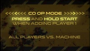
To start a game in co op mode simply hold the start button down for a few seconds when adding player 1.  The game will flash a confirmation on the LCD and a callout saying that co op mode is enabled.  This is standard co op mode, which is all additional players are working together as a team to destroy the 9 reactors.  All scores are shared, no extra balls, replays, or high score tables are enabled.  It is your team vs. the future, that is it.

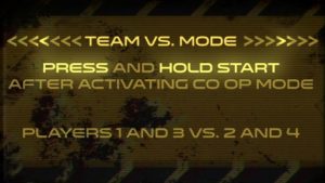
If you would like to make things a little competitive in co op mode, there is another co op type that can be selected.  This other mode is team versus co op mode.  This mode can be activated by pressing and holding the start button for a few seconds after the standard co op mode is enabled.  This mode requires 4 players and will revert back to standard co op if not enough players are added before shooting the first ball.  In this mode, players 1 and 3 will be going up against players 2 and 4.  This is also called “odds vs evens” in some tournaments.  All progress and scores are shared between each of the players within their respective teams.  Just like standard co op, no extra balls, replays, or high score tables are enabled.

As with any software release, please let us know if there are any show stopper issues on your game.  Please contact [email protected] and we will get back to you asap.  Thank you and enjoy!

Change Log:
v1.2.0.00 – 04/08/2018 – Scott Danesi

## Bugs Fixed ##
– Quickshot video lag issue fixed.
– Adjusted debounce on top CORE rollovers, now will not miss hits off the upper flipper
– Fix for stuck 4x multiplier in multiball
– Lightshow stuck lamp issue fixed
– Flipper hold boost PWM patterns changed to minimize heat and noise
– Ball save issue after reactor destroyed fixed
– Fixed ball save issue during multiball
– Major performance update for lightshows – Thank you Josh Kugler!
– More secret skillshot bug fixes (now worth 100,000 points)
– Lightshow handling updates to prevent rare stuck on lights issue
– Lots of other little things that were bugging me that are not worth mentioning

## Features Added / Modifications ##
– Added target free game setting in coin op settings for operators to control advanced match logic
– Co Op Mode added!
– Team VS Mode added!
– New Jackpot voice callouts
– Kill target locations now regenerate if you hit 20 unlit kill targets – protects location
play if a target gets broken. This is also a setting in the service menu
(Critical Target Miss Threshold)
– Sound volume setting no longer in service menu
– Removed trough jam and warning messages from LCD
– Service Menu now highlights settings that have been changed from the default value
– Super spinner now gets harder to achieve each time it is earned
– Orbit combo logic and scoring reworked now with multipliers!
– Bonus tally can now be skipped to the total bonus screen by pressing both flipper buttons
– Ball save for multiball is now independently adjustable in the service menu
– Ball save on reactor destroy now adds 5 seconds to the current ball save or starts a new 5 second
ball save

## Download Link ##
https://drive.google.com/open?id=1RDnDQzY5JvBZn7BVcrCvYDZcqVoa6cjJ

Code Update Procedure:
WARNING: Updating code on your game will reset your audits and settings on the game after the update procedure. However, these audits and settings are automatically dumped to the USB stick as a backup for your reference. I am planning to add functionality to save audits within the game in the future.

Step 1: Download the latest “pkg” file from the link above.
Step 2: Copy the “pkg” file to a USB flash drive. Do not change the name of the file, should be named “tna-gamecode.pkg”.
Step 3: Power off the game and remove the backglass.
Step 4: Insert the USB flash drive into an open USB port on the PC located on the right side within the backbox.
Step 5: Power on the machine, a message should appear saying that the software is updating.
Step 6: Once the code update is complete, remove the USB flash drive and restart the machine.